|
|
||
|
|
|
|
|
|
||
Wiring
|
|
|
||||
|
|
Copyright © 2002-2017 John Mayer. All rights reserved. For reuse policy see Reuse Policy Wiring
This section is pretty big, and may provide more technical detail than a "non-techie" wants. However, for those implementing their own system most of the required info should be here for a successful install. Warning: if you are not comfortable with electricity, do not attempt wiring your own system. Get help. There are five main areas of wiring:
Some inverters have a wire pigtail internally that you connect your AC lines to (not many have this these days). If the inverter does not have terminal blocks for the AC input/output connections, use twist-on wire nuts, like in a residential electrical connection. If you have to use twist-on connectors, make sure you tape them to the wires securely to prevent loosening from vibration. You can also use the newer "push in" connectors with solid wire - these actually secure the wire better.
For now, I will assume you are connecting your rooftop panels in parallel, and that you are using 12-volt panels (nominal rating). We will discuss higher voltage panels and serial wiring a little later.
Just like batteries, solar panels come in 12 volt (nominal) and "high voltage" versions. The 12 volt panels have a Vmp of around 17-19 volts (no more, typically). The high voltage panels vary in Vmp from around 26 volts to more than 35 volts. Why would you use higher voltage panels? Two reasons: first, larger panels typically come in higher voltage, so if you want 175+ watt panels you have more choice in higher voltage. Second, higher voltage panels mean less voltage drop on the way to the controller. A technically superior design would be to use higher voltage panels and a solar controller that can convert the output voltage to 12-volts. This allows you to use smaller wiring, or have longer wire runs from the roof to the controller.
One caution on daisy chaining the wire runs between panels. This is, in general a bad practice if you have a lot of panels. The reason is that you are using the terminal on the panels to pass all the current from one to the other....the last panels will have current across the terminals that they are not rated for (in some cases). It is better to use a combiner box and "home run" all the wiring directly from the panel to the combiner.
I prefer to use the combiner, but it does increase the cost
slightly, and complicates the initial installation a little. Locate
the combiner centrally, near the panels, but try to minimize the
wire run from the combiner to the solar controller. You can
then run one larger wire from the combiner down to the controller.
Look at the voltage drop tables/interactive calulators in the Solar Regulator section to
calculate the wire size required and then use one size heavier.
I prefer to use a minimum of #4 wire for the run
to the solar controller, which is sufficient in almost every case
(but not all cases - you MUST use the voltage drop tables to ensure
your wire size is correct). Even if #4 is not required, it gives you
some room for growth and does not cost that much more.
You
can find various types of small distribution hubs several places,
including at many Wal-Mart's in the automotive audio section. Or
order them from the internet sources in this article. (Try
www.solarseller.com
look in section
57, Cat# PDB-175-SIX, about $29). To build
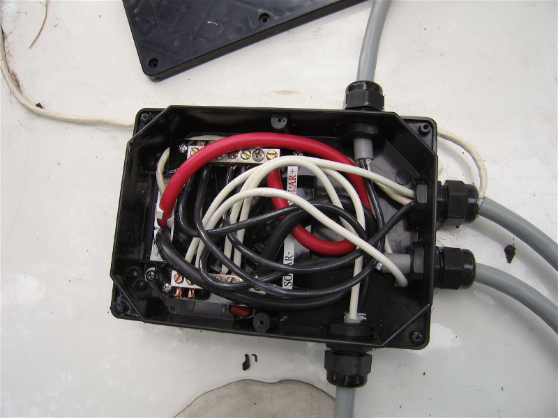
a "home made" combiner I use a plastic outdoor junction box, which has a
removable lid, with a gasket. It is easy to drill the appropriate
sized holes in the sides for routing wires. Use weather-tight wire
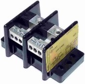
clamps. I like to use hubs that have at least four outputs (which
you will use as inputs for the wires from the panels). You can
usually double the wires up, if required. You need one hub for + and
one for -, or you can buy a dual hub, which is the one shown.
Position it in the box so you can tighten the set screws. Epoxy
it into the box, when you are satisfied with the layout.
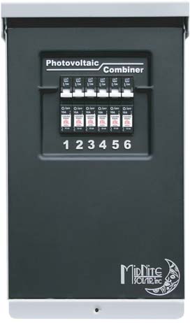
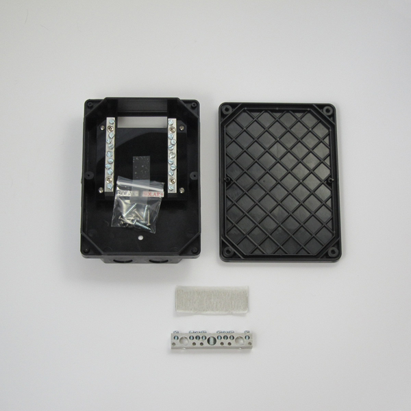
The alternative to building your own is to buy a simple ready-made combiner box from AM Solar. Check the product section for combiner boxes. The new AM Solar combiner box is the 4/2 box. It will take much heavier wire than the previous boxes available from them. The old boxes would only take #6 wire - these boxes will take #2 easily. You can also find combiners from Outback and Midnite Solar that contain DC-rated breakers in them. These are weather-tight enclosures, but are intended for vertical mount. They can be mounted at up to a 45 degree angle on the roof without a problem (with the back facing the front of the RV, so water is never forced into the lid). The advantage of using the combiner with the breakers is that you can easily test each panel, or string of panels. Plus, each panel is protected from a short or catastrophic failure of another panel. I think the $100 or so that you will spend on the combiner with breakers is well worth it. When adapting these breaker boxes to roof-mount I often position them behind and air conditioner cover to protect them from wind-forced water. An alternative to putting the combiner on the roof when you are using a high voltage system is to place the combiner in a "close" storage compartment and run the #10 wire from each of the panels (or strings) down to it. This is especially nice with the breaker boxes, since it negates any water entry to them. This works well ONLY IF the voltage is high enough so that there is not more than 2% voltage drop to the combiner. Use the voltage calculators.
For the home-built and AM Solar combiners, I try to bring the wires in from the sides of the box that will face the sides of the RV, or from the rear. That way if the entry holes are not perfectly sealed there is less chance of wind forcing water into the box when driving. I bring the single entrance wire (going to the controller) out the back. To hold the box to the roof, use adhesive caulk compatible with your roof material. If you have a fiberglass or aluminum roof you can use adhesive silicone caulk. If you have an EPDM rubber roof, or a vinyl roof use the Dicor adhesive caulk designed for that application - do not use silicone on an EPDM roof, because it will not stick. With Outback or Midnite Solar combiners the wire routing is the same as a standard electric subpanel - from the bottom.
Use a waterproof connector on the home made boxes to secure the cables into the sides or back (as described above). These connectors are available at Home Supply stores. In the pictures above, the combiner to the far left is a Midnite Solar 6-position combiner. It can take six parallel-wired panels, or 6 strings of series-wired panels. There is a water-resistant cover that is not shown. The next two boxes are from AM Solar. The middle one is the small CB combiner box that can take four panels in (or double up on the terminal strips for more). With more than four panels I do not recommend the CB - it is too tight to wire. The third box is the new (larger) combiner box from AM Solar - it is their best box and I highly recommend it if you are not doing breakers. There is plenty of space for lots of wires, and it will easily handle any size up to 1/0.
To hold single wires on the roof I use "puddles" of the appropriate adhesive caulk - embed the wires in the puddle. I put the puddles about every 3-5 feet along the wire run. Once the caulk sets, add a little to the top. I've been doing this for years, and have never had a wire come loose. For the "bundle" of wires you might have if you combine the individual wires of multiple panels on the way to the distribution hub (tie wrap them together), use a combination of caulk and one tie-wrap with a screw slot to secure them. Cover the single screw with caulk. Use caulk alone to secure the rest of the bundle to the roof. All rooftop wire should be UV resistant "tray cable". The solar wire extensions you will use with MC-type connectors is tray cable, as are the pigtails from the panels. Or, you can run conduit if you want, but this is really overkill, and much harder to install. I have very rarely seen conduit on the roof in an RV installation. I use 10 gauge wire between the panels, or from the panels to the (rooftop) combiner, and usually #4 welding wire to run down to the controller. Unless you have an unusual distance from the combiner to the controller this is usually more than sufficient. If you have a low voltage, high-amperage set of panels (lots of panels in parallel) then the #4 may not be sufficient, and you may have to wire the panels so you increase the voltage, and decrease the amperage. More on that technique is discussed below.Or, use much larger wire. In any case, use the interactive voltage drop calculators, or the voltage drop tables on this website to determine the size required. Some RV's have "solar prep" packages. These typically have 10 gauge wire installed by the manufacturer from the roof to the solar controller location. This is marginal in most circumstances plus it may not terminate in the location that you want it. You will have to decide if you want to use this wire, or run another wire that better maintains voltage. Consult the voltage drop calculator and estimate the length of the wire run. In some cases it is easy to add a second wire - in which case you could run a second 10 gauge wire in parallel to the "solar prep" wire supplied by the manufacturer. Or you could just run the 4 gauge wire (or approriate size) and abandon the manufacturer's wire. Wire size and connector quality are particularly important when using an MPPT controller. Heat and bad wire connections will cause an MPPT controller to operate far below its rating, negating any advantage to using it instead of a non-MPPT controller. The voltage-drop calculator will tell you what you need to use. Without using the voltage drop calculator you are simply guessing. Wire for a 2% or less voltage drop - you should strive for 1%. If the input terminals on your solar controller will not accept the wire size you use, simply clip some of the fine wire strands off until it fits. This won't affect anything. 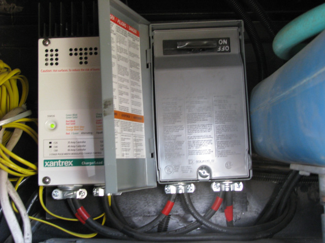 From the solar controller
to the battery bank I often am able to use the same #4 AWG welding wire, depending on the length of the
run. It is critical to minimize voltage drop from the controller to
the battery bank. Make sure that your wire is heavy enough. You MUST
use the voltage drop calculators - especially with an MPPT
controller where the current coming out of the controller is far
greater than what is going into it. Aim for
a 1% drop. There is a fuse installed in this line. On small systems (one
or two panels), I use automotive "Maxi" fuses instead of the glass fuses usually supplied in
solar installation kits or with some controllers. They are easier to
install, and easier to insert fuses. It is also easier to "pull"
them if you want to service the lines. This should only be done on
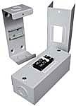
smaller systems. With larger systems you can use an air conditioner
disconnect box with two legs of service on it (shown on the left). One leg (and
fuse) handles the input side of the controller - the wire from the
roof. The other leg (and fuse) handles the output side of the
controller - the wire to the battery. So the wire goes from the roof
into the disconnect, then to the controller, then back through the
disconnect and on to the battery. This allows you to isolate
the controller from all power by simply pulling the disconnect
handle out. You can find these boxes at any Home Depot or Lowes in
both 40 amp and 60 amp ratings. The SquareD boxes are DC rated. Make sure you use the appropriate
fusing and that it is DC-rated; it is likely a larger fuse on the
output side. From the solar controller
to the battery bank I often am able to use the same #4 AWG welding wire, depending on the length of the
run. It is critical to minimize voltage drop from the controller to
the battery bank. Make sure that your wire is heavy enough. You MUST
use the voltage drop calculators - especially with an MPPT
controller where the current coming out of the controller is far
greater than what is going into it. Aim for
a 1% drop. There is a fuse installed in this line. On small systems (one
or two panels), I use automotive "Maxi" fuses instead of the glass fuses usually supplied in
solar installation kits or with some controllers. They are easier to
install, and easier to insert fuses. It is also easier to "pull"
them if you want to service the lines. This should only be done on
smaller systems. With larger systems you can use an air conditioner
disconnect box with two legs of service on it (shown on the left). One leg (and
fuse) handles the input side of the controller - the wire from the
roof. The other leg (and fuse) handles the output side of the
controller - the wire to the battery. So the wire goes from the roof
into the disconnect, then to the controller, then back through the
disconnect and on to the battery. This allows you to isolate
the controller from all power by simply pulling the disconnect
handle out. You can find these boxes at any Home Depot or Lowes in
both 40 amp and 60 amp ratings. The SquareD boxes are DC rated. Make sure you use the appropriate
fusing and that it is DC-rated; it is likely a larger fuse on the
output side.
With higher output (larger) systems, the #4 cable you used from the roof to the controller may not be enough for the run to the battery bank. Make sure you run your numbers through a voltage drop calculator. On a 60 amp controller you should use #2 or larger to ensure that there is no voltage drop. Even if the current implementation does not require the larger wire, you may want to use it so that you don't have to rewire if you add panels - in other words, wire for the max output of the controller you are using. Use the voltage calculators. You need to ensure that you meet BOTH ampacity standards and voltage drop goals. Ampacity charts do NOT account for voltage drop! Remember that an MPPT controller can boost the amperage quite a bit under ideal conditions. Make sure you understand how to figure this and take it into account. It helps if your solar controller is located close to the battery bank. An MPPT controller can make up for voltage loss from the roof fairly effectively, and properly output the correct voltage for the battery charge stage. But if it is too far from the battery bank you will have voltage drop between the controller and the battery bank, and there is no "machinery" like the controller to compensate for this. Solar Array Wiring Considerations In a small solar system that is typical of an RV it is pretty simple to design the array configuration. Most systems on RVs are 1-4 panels, and typically 12-volt panels. For discussion purposes lets say they usually have an output of about 135watts each, with an Isc of about 8.4A. Isc is the "short circuit" current (I) of the panel in ideal test conditions. It is the very max a panel can output, and is used for calculating wire sizes and controller sizing. On RVs, these panels are often wired in parallel - all plusses are joined together on the roof (and the negatives) at a combiner box and a single pair of larger wires is used to bring the power down to the solar controller. When wired in parallel in this fashion the voltage stays the same (Vmp of 17.7), and the amperage is cumulative. In this example, 8.4A*4 panels=33.6 amps. You have to send this amount of current (power) down to the controller. At this low a voltage (12-volt nominal) you have to be careful of the wire size so that the voltage is not reduced too far over the length of the run - especially with an MPPT controller that "likes" high voltage. However, the advantage of the MPPT controller is that the current is lower and thus there is less voltage drop over the same distance than the lower voltage/higher current of a 12-volt nominal panel.
Lets take an example of 20' of wire run to the controller from the combiner box on the roof - which would not be atypical on an RV. Using the voltage drop calculators for 35A and 21' and you will find you need #2 wire. Not good, since that is a pretty big wire size and expensive. But now lets look at reality: your panels are flat on the roof, and not well ventilated. They are not going to output the Isc, or likely even the Imp (current at "max power"), but lets use Imp at 7.63A * 4 = 30.52A. You are now pretty close to the (minimum) #4 cable that I recommend as the minimum. And in reality you will probably never see 30A off the array - you might out of the solar controller after boost though. But that should be a short run from the controller to the battery.
Since we are marginal in the configuration above, lets look at the effects of running these same panels in series with a MPPT controller. Remember, all of the larger MPPT controllers are rated to handle a max of 50-150 volts. In reality, if you follow NEC codes you are constrained to less - say 145 volts.
With the same four panels in series (by the way, these are Kyocera KD135GX-LPU panels in the examples) the voltage combines, but the amperage stays the same. Exactly like with batteries. So in this case: Vmp = 17.7V * 4 = 70.8V, and the current stays at Imp 7.63. So you are sending 7.63A at 70.8 volts to the charge controller. And that fancy MPPT controller can take that high voltage, perform some magic on it, and output it at nominal battery voltage (lets say 14. 8 Volts on bulk charge with flooded cell batteries) and whatever amperage is appropriate - generally the max it can push out in bulk mode on a small array like this. In this case lets say it is outputting the 30A from above and boosted it 10% to 33 amps. It is easy to see that with a wire run of 20' and a current of only 8 amps (I rounded up) you have no issue at all with #4 cable to the solar controller from the roof. So there is a lot of benefit to the higher voltage. And you can only do that with an MPPT controller.
But there is an additional complication. The MPPT solar controllers are most efficient when the voltage coming in is about 2-2.5 times the nominal battery voltage, more or less. They lose efficiency in down converting really high voltages on input to really low voltages on output. So for the most efficient array configuration we might want to reduce that voltage some and get it closer to 35V. We can do that with two panels in series instead of four (this is referred to as a "string") which will output Vmp * 2 = 17.7 * 2 = 35.4V. Much better. Now we have two strings of serial panels on the roof, and we will parallel them together at the combiner box: 35V @ 15A. How did I get that? Each string is 7.63A, since the two panels are in series. And when you parallel the strings the voltage stays the same, but the Amps adds: 7.63A*2=15.26A. Consulting the calculator we see we have no issue with the distance or the cable size using #4.
You should only put similar (exact) panels in series. Voltage specs (Vmp) for all panels in the string (and all strings in the array) should be within 0.2-0.3 volts of each other (note the decimal point). Otherwise you introduce inefficiencies and reduce output.
When wiring panels in series you must match the IMP ratings. The rating of the entire string of panels is the lowest Imp in that string. For series strings the voltage adds and the current is limited to the lowest Imp rating. Example: two 180 watt panels with Imp=10 and Vmp=18. One 90 watt panel with Imp=5 and Vmp=18. If you series these three panels you will have a string with 54 volts @ 5 amps. You can see how that affects the expected output of the string. In the example it would NOT be 180+180+90=450 watts. Instead it would be 54*5=270 watts. Not what most people would expect.
And finally, series-wired panels that are tilted must all be tilted or you will kill your output. It is, in effect, similar to shading a panel. So if you intend to tilt a series string, make sure you tilt them all or you will be surprised at how much you did NOT improve solar harvest by tilting.
When wiring in parallel the current will add: Imp+Imp+Imp. Your voltage is then limited to the lowest voltage in the array. So, like in the example above, if you put a low voltage panel together with higher voltage panels (say a 16 volt panel with a bunch of 18 volt panels), then what you get is effectively a16 volt array.
All of this applies to strings of panels, as well. Consider a string of panels as a single panel, electrically. So you need to be concerned with matching strings. Mostly, strings are joined to other strings in parallel, so the "parallel requirements" apply. The current of each string will add, and the voltage will be limited to the lowest voltage of the strings. This may not be what you expect. Make sure that your strings are balanced, or, alternatively, on a large system an "odd" string can be run to a separate controller and not paralleled to the other strings.This works fine, as long as the controllers are networked.
You can see that it is not real simple to properly design a higher-powered system. But if you take your time and understand the concepts it is not rocket-science.
MC Connectors
MC connectors are a mixed blessing, IMO. They greatly simplify wiring, but they also add cost. Personally, I'd rather have a J-box; that is just me...Regardless, we are stuck with MC connectors. They do make for a fail-safe connection and are far less prone to installer error.
There is a positive and negative MC connector on each panel. You use MC extension cables to extend the wire run back to the combiner box. Buy an extension cable twice the needed length and cut it in half - that gives you a separate male and female MC connector, with a bare wire end to connect at the combiner box. If you are running strings of panels then for the serial connections between adjacent panels you can just plug the panels in directly to each other (as appropriate), and then run the opposite end(s) +/- back to the combiner. The extensions come with 12 gauge and 10 gauge UV resistant wire - make sure you get the 10 gauge. The pigtails from the panels are almost always #10.
This permits a 2-1 reduction.
With the MC4 latching connectors you need an unlatch tool, or you will struggle getting the connectors apart. This can be bought with the connectors. The MC4 connectors are waterproof, but it is still a good practice to wrap them with tape when finished.
Cables
and Battery Connections I always build my own cables, and I recommend
that you do the same. First, it is cheaper and you
generally get a
better product. Second, it is difficult or impossible to get the wire
lengths and orientation of the lugs correct if they are built
commercially.
The best cutters are the ratcheting
cable cutters. You can find them on Amazon for around $35. They cut
up to 240mm cable - which is larger than 4/0. Search on "ratcheting
cable cutter". I'd put in a link but it will go bad....
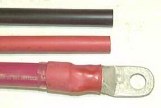
Note that these lugs have closed fronts, and are tin-coated for
corrosion resistance. They are pure copper underneath. The lugs, crimper
and battery extension posts (see below) are available at
Solar Seller,
The Solar Biz, or at
Wrangler Northwest Power. You will find it
useful to call Wrangler Power (800-962-2616) and order their catalog.
They have high quality parts, regulators, high output alternators,
isolators, lugs, 12-volt fuse centers, etc. described in the catalog.
Their website is very difficult to use. Solarseller has better prices
than Wrangler, if they have the part. If you can't find wire locally you
can get it from Welding Supply.
They have colored wire for a reasonable price.
After crimping you apply an adhesive heat shrink tube (color coded,
of course) over the lug. Once melted, the adhesive totally seals the
barrel of the lug and greatly minimizes future corrosion. You will
probably have to mail order the
adhesive heat shrink tubing
. For battery interconnections and the run to the
inverter from the battery bank you can buy regular battery cable, or the
highly flexible battery cable. For runs from the rooftop solar combiner
to the solar controller the industry norm is to use welding cable -
since it is highly flexible and far easier to handle. This is easily
obtained at any welding supply house. Buy it uncut and cut it yourself
when building the cables. You can also use welding cable for battery
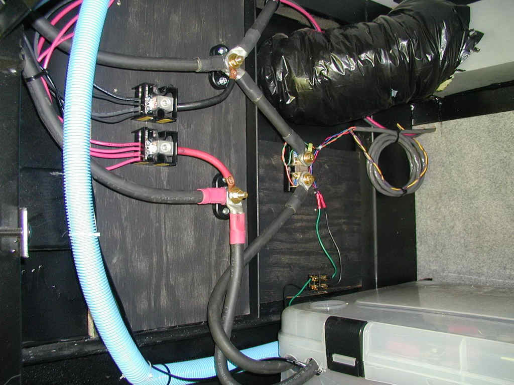
interconnects and the run to the inverter. Hooking up the inverter cables is not difficult but there is only one
correct way to do it. The positive feed originates from one side of the
battery bank, and the negative feed from the opposite end (battery 1 and
battery 4, in a 4-battery system). Diagonally
loading the bank ensures that all batteries are drawn down equally. If
you hook both leads to one battery - no matter which one - that battery
will be supplying more of the load than the others, and will get more
charge than the others. Rub a little Oxguard
on the lug before bolting it down. You may have to drill the lug to a
larger size, depending on the lug and the battery. You might want to
measure the battery terminal bolt size before ordering lugs. Route the cables from the battery bank to the
inverter either parallel to each other and touching, or twist them
around each other. This minimizes interference from the magnetic field
that will emanate from the cables.
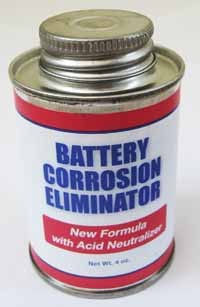
When you are done connecting the battery wires put a corrosion eliminator on them. The one shown is available at Backwoods Solar (and other places). It dries solid so is not slimy. Use this only on the battery connections - do not place it elsewhere. Many people will tell you it is always best to solder, but that is not true. It depends on the circumstances. In dealing with a mobile environment that is full of vibration soldering can be problematic. Soldering a wire makes it stiff and inflexible. It can easily break over time where the solder joint meets the unsoldered wire. Look at marine and aviation wiring - it is rarely/never soldered. Soldering is also not UL approved. The issue is that if the wires heat up the solder joint will melt and the joint will fail - often causing a fire. Here is my advice. Take it for what it is worth. I solder all small wires that absolutely need a good connection - brake wires in trailer brake controllers are an obvious choice for soldering. In this case the benefit overweighs the potential downside. I would never solder a wire bigger than #8, and generally I avoid soldering lugs on any wire. For large solar or high-amperage wires (#6 and bigger) do not even think about using a soldered connection. It is far better to PROPERLY crimp the wire.
Your inverter manufacture will provide a chart that will tell you
the requirements for wire sizes from the battery bank to the
inverter. They will also specify the fuse size required on the
positive line at the battery. You need to follow the manufacturer's
instructions carefully. If you under wire this connection you can
start a fire or damage the equipment. Don't cheap out and delete the
fuse. The fuse protects your RV from fire if the inverter
malfunctions. You definitely don't want your RV burning down.
Lets assume you are using a 2000 watt inverter. In this case, you
will use 2/0 or 4/0 cable to connect from the battery bank to the
inverter, depending on the distance. The shorter the distance, the
better, but your inverter can be as much as 10-12 feet (of cable
run) from the battery. Use the heavier 4/0 cable if you are even
close to the rollover point between the cable sizes. Bigger is
always better when it comes to cabling the battery/inverter.
The 300-400amp fuse (use the size specified by the manufacturer)
should be mounted within 18" or so of the battery. You can mount it
in an appropriate fuse holder, or if you use the right fuse you can bolt it directly to the
positive post of the battery if you have no method to mount a fuse
holder. The fuse holder is preferred.
The wires to the inverter will put out a magnetic field that can
affect electronics in the RV - especially the AM band on the radio,
and potentially TV's. Usually, this is not a problem, but it can be.
To minimize the potential for this interference you can twist the
cables around each other, or parallel them together. It is usually
easier to parallel them together, using a tie-wrap every foot or so.
This results in the magnetic fields canceling each other out.
AC Wiring - Interfacing to Your Load Center
There are some major considerations in interfacing to the load center (the circuit breaker box) that can drive the entire system design and complexity. The first is determining if you will use an inverter with a transfer switch rating that matches the capacity of the main breaker in your load center. In other words, are you using a 30 amp-rated inverter in a 30 amp RV, or using a 30 amp-rated inverter in a 50 amp RV? There is a major difference in system design and capabilities. If you are not installing a sub panel, it is best to match the rated capacity of the inverter transfer switch to the RV AC capacity - a 30 amp inverter with a 30 amp RV; a 50 amp inverter with a 50 amp RV. You pay more for a 50 amp inverter, but you will make it up on ease of installation and system design considerations. The second major consideration is if you will install a sub panel for the inverter loads. Use of a sub panel to isolate the inverter loads is technically the best design, but practical considerations may lead you away from this implementation. The use of a sub panel isolates the lower power circuits that you will supply inverter power to, from the high amperage circuits that are impractical to support with a battery bank. Typically, these high amperage circuits are the air conditioner's, the electric hot water heater, the converter (if it is left in the system) and any other high-amperage appliance circuits, including the refrigerator. In addition, the 120-volt lighting circuits are usually left in the main panel. Circuits that are moved to the sub panel are typically the wall outlets and the microwave. This includes the entertainment center, since this is typically driven off wall outlets. In most installations you will be adding a subpanel. There are very few inverters on the market that will transfer 50 amps on two legs (typical RV service these days). Go Power! has one (the IC-2000) which is a pure sine wave product. But there are very few selections on the market, as of 2017. AC Wire Types
RV manufacturers all use regular house wire for the AC feeds in RV's. The exception is the actual shore power cable coming in, which is usually stranded wire. Type NM wire is solid copper wire and is generally what is used for the AC distribution wiring.
However, note that the NEC would require stranded wire to be used in RV construction, but not a SINGLE manufacturer of motorized or towable RVs does so. They use standard residential wiring and wiring techniques for the AC distribution system. This causes "issues" down the road (literally, down the road). Mostly in vibration loosening connections in loadcenters and transfer switches. It is a good idea to add checking these connections to your yearly maintenance schedule. A better wire is boat wire, which is stranded and tinned. Stranded wire stands up to vibration better, but is much more expensive. It is required for marine use by Coast Guard regulation. In the past I usually continued to use standard house wire because the coach is already wired with it, so upgrading just a portion of it is not usually justified. However, I have recently reconsidered this due to the number of burned and loose fittings I have seen in RVs with solid wire.
Grounding
|
||||
 A
neater solution to the requirement to be able to isolate the
controller is to use a DC-rated breaker box and fuses. These days I
almost always use a Midnite Solar
A
neater solution to the requirement to be able to isolate the
controller is to use a DC-rated breaker box and fuses. These days I
almost always use a Midnite Solar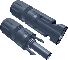
 If
you parallel all the panels (or use two strings) then you might want to
reduce the wire runs to the combiner. You can do that with MC "Y"
connectors. They come in male and female.
If
you parallel all the panels (or use two strings) then you might want to
reduce the wire runs to the combiner. You can do that with MC "Y"
connectors. They come in male and female.
 You also need a large crimper for the magna-lugs you will use.
The picture on the left is an example of a hammer crimper that works
acceptably well.
You put the lug into the anvil and whack it with a maul. The alternative
to crimping is to solder the lugs (more on soldering below). If you decide to solder I recommend
Fusion lugs. These have solder and flux in the barrel of the lug. You
stick the lug in a vice, heat it with a torch and when the solder melts
insert the wire. The problem with this is that it is often difficult to
get the wire in, and you have to fool with it. Difficult when you have a
hot lug and limited time to get the wire in. I prefer to crimp.
You also need a large crimper for the magna-lugs you will use.
The picture on the left is an example of a hammer crimper that works
acceptably well.
You put the lug into the anvil and whack it with a maul. The alternative
to crimping is to solder the lugs (more on soldering below). If you decide to solder I recommend
Fusion lugs. These have solder and flux in the barrel of the lug. You
stick the lug in a vice, heat it with a torch and when the solder melts
insert the wire. The problem with this is that it is often difficult to
get the wire in, and you have to fool with it. Difficult when you have a
hot lug and limited time to get the wire in. I prefer to crimp. 
 You also need an antioxidant, which is used on the wires before
crimping. This helps prevent corrosion. Apply to the wires and rub in. Squirt a little into the lug
before crimping. You should put antioxidant on all wires - no matter the
size - before crimping. One brand name available at Home Depot/Lowes and
Ace Hardware is Ox-gard.
You also need an antioxidant, which is used on the wires before
crimping. This helps prevent corrosion. Apply to the wires and rub in. Squirt a little into the lug
before crimping. You should put antioxidant on all wires - no matter the
size - before crimping. One brand name available at Home Depot/Lowes and
Ace Hardware is Ox-gard.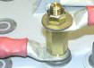 If
using an ANL-type fuse, mount the fuse in a fuse
holder. On vehicles this is often difficult to do and still keep the
fuse within a (max) of 18" from the battery. If you have no
mounting location then you can use a different type fuse and mount the
fuse directly to the battery post on vehicles (look at the JJN type). On RV's I almost always
use a fuse holder, since there is usually plenty of mounting room.
Either approach is acceptable. More detail on fuses and connections -
including some innovativefuse holders - can be found in
If
using an ANL-type fuse, mount the fuse in a fuse
holder. On vehicles this is often difficult to do and still keep the
fuse within a (max) of 18" from the battery. If you have no
mounting location then you can use a different type fuse and mount the
fuse directly to the battery post on vehicles (look at the JJN type). On RV's I almost always
use a fuse holder, since there is usually plenty of mounting room.
Either approach is acceptable. More detail on fuses and connections -
including some innovativefuse holders - can be found in
 If
you do decide to use solid wire in an RV make sure you tape the
wire nuts to the wire (when using wire nuts). A better solution than
standard wire nuts for solid copper wire ONLY is the newer "push-in"
wire connector shown in the picture. These are available at all the
home stores. I use them exclusively for electrical work now. Using
tape or the push-in connector will prevent vibration from loosening
the connection, which it can, over time.
If
you do decide to use solid wire in an RV make sure you tape the
wire nuts to the wire (when using wire nuts). A better solution than
standard wire nuts for solid copper wire ONLY is the newer "push-in"
wire connector shown in the picture. These are available at all the
home stores. I use them exclusively for electrical work now. Using
tape or the push-in connector will prevent vibration from loosening
the connection, which it can, over time.
| Link 1000 above, AC line monitor below - click to expand |
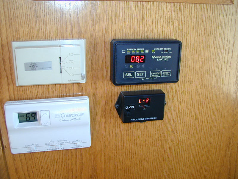 |
These are the minimum functions you need, in my opinion. Anything else is optional, but you may feel like you need it. Personally, I like to know everything that is going on, but realistically it is not required. For example, it is nice to have a monitor for the solar controller, but since there is really nothing to control (other than possibly equalization), it is really not necessary. You can see the charge amps and voltage on your battery monitor. The only measurement that is missing is input amps and voltage coming into the regulator. This is interesting if you want to see how much "boost" you are getting from an MPPT controller, or just to see how much current is lost in wire runs. My solar controller display is behind a door, and I rarely look at it.
You need to place the displays where you will see them. They are no good hidden away, unless you discipline yourself to look at them. Our displays have varied based on the RV we have had. In many rigs they were on a side wall, where they are easily seen. In another rig they were in the hallway to the bath. In our current coach our controls are all behind a door. You will find you will refer to the battery monitor often, especially when you are learning the operational characteristics of the system.
In my opinion, and it is shared with many industry experts, you
absolutely need to measure cumulative amp hours of your battery
bank. There is simply no other way to effectively know the current
state of the bank. If the instrumentation that is available for the
inverter does not provide for this, then you need to augment it. If
you are going to augment your inverter monitor/control, then buy the
cheapest control panel available for the inverter (making sure that
it allows control of all functions). Augment the control functions
with monitoring functions provided by a TriMetric TM2030 monitoring
system. This provides all the monitoring functions you will need for
your entire system, and is commonly available for around $150,
including a 500 amp shunt. You can check out the TriMetric at
Bogart Engineering. You can buy the TriMetric at
Solar Seller. If you want
to monitor more than one power source individually, check out the Pentametric battery monitor from Bogart. It can
monitor 3 charging sources at once. But it is not cheap. Don't view
the purchase of the TriMetric as spending an "extra" $150. If you
can not determine the state of your system accurately you will have
continual problems down the road. You might also look at
the Victron battery monitor. It has a very nice display and is
around the same price as the Trimetric. Both are excellent - I'd
probably buy the Victron if choosing today (2017).
I'm often asked if multiple instruments can be wired to a single shunt. In general, the answer is "yes". Simply follow the instructions for wiring the (new) instrument onto the existing shunt.
Recommendations
On a 30 amp RV I would wire the inverter in-line and power the
entire load center. This makes installation simple and ensures that
the circuits you want powered are available, since all circuits are
available when inverting. I definitely would not bother with a sub
panel.
On a 50-ampere RV I would add a sub panel if it was at all possible. There are so many advantages to this approach that it makes it worth the extra trouble. This would permit you the flexibility of using a 30 amp inverter if you choose. If a sub panel was not possible, or you choose not to go through the headache of installing it, I would use a 50 amp split-phase inverter that allows for "in-line" installation (if you can find one). As of 2012 I know of no inverters currently on the market that allow 50 amp pass thru on two legs of service. The "60 amp rated" inverters actually restrict EACH leg to 30 amps. Update (2017): the Go Power! IC-2000 sine wave inverter does allow dual 50 amp legs to pass through.