 |
Copyright
© 2002-2009 John Mayer. All rights reserved.
For reuse policy see Reuse Policy
Warning:
In this section I describe various wiring techniques and
electrical designs. These generally conform to the national electrical code, but it is up to YOU
to determine their suitability to your situation. DO NOT take this as
electrical advice, only as possible design considerations. If you do not
understand basic residential wiring and 12-volt automotive wiring then
you should not undertake any of
these implementations without further help and advice. If in doubt be
sure to get help. Electricity is dangerous. The high amperage DC
electricity obtained from the large battery banks described here is
suitable for welding and can easily kill you. Do not underestimate the
danger involved in working with DC power!!
The information I present here is intended to get you
started - it is not intended to give you detailed designs that you can
implement directly! Every RV implementation is different, and will
require specific design goals to be addressed. However, most of the
major issues and considerations are discussed here. If you understand
most of what is presented here then you will likely end up with a good
system - even if you have someone else implement all or part of it.
In this
Section:
Presentations
Introduction to Solar
Solar Panels
Solar Controllers
Xantrex Inverters
The Battery Bank
Wiring
- Rooftop and Solar Controller Wiring
- Solar Array Wiring Considerations
- Battery to Inverter Wiring
- Interfacing to Your Loadcenter
- AC Wire Types
- Grounding
- Neutral Bonding
- Installing a Sub Panel
- Powering the Entire Loadcenter
- "Splitting" a 50-amphere Loadcenter
- Monitoring and Control
- Recommendations
Installing a
30-Amphere Inverter in a 50-Amphere RV
AC Circuit Protection
Sample Systems
I'm assuming that you have a basic understanding of both 12-volt and
120-volt power. There are many excellent tutorials and books on both
subjects. I won't repeat the information here, but leave it to you to
explore on your own if you don't understand the basics. For basic
12-volt electrical info, try
Mark Nemeth
Electrical Info which
is Mark Nemeth's article on 12-volt power. For wiring techniques and
parts check the
The Truck Electrical Center section of
this site. The
information there is oriented to upgrading an HDT truck, but is
generally applicable to RV's.
For an understanding of various RV and house connectors, and proper
wiring, check out
http://www.myrv.us.
This will give you an understanding of basic RV electrical service, and
how it differs from residential electric. You might find
Bob
Hatch's website
useful as well. He describes upgrading a 30 amp RV service to 50 amps.
Even if you are not performing this upgrade, understanding what he did
will expand your knowledge of RV electrical systems.
If you have a basic understanding of AC/DC electricity then you should be
able to design a reasonable system following the recommendations in the
sections below. The system designs and components used are only examples,
and need to be modified to meet your needs. You need to complete the
entire design before you start implementation or you might find
your system unable to meet your future expansion needs.
If you need help with system design you can work with a single vendor for
most of your system components and they should be able to provide design
help. The best thing is to work with someone who understands the special
needs of RV's. My first choice would be AM Solar (Greg Holder). Their
business is RV solar, they can supply almost all the required solar parts,
their prices (for the most part) are reasonable, and their preconfigured
systems are very nice;
AM Solar.
John Palmer (Palmer Energy Systems,
Palmer Energy) also
specializes in RV solar systems.
For parts and design help from the
residential market try (first)
Northern Arizona Wind and Sun. They have an
excellent forum with true experts posting on it, and their store has
reasonable prices. Do not underestimate what you will learn from reading
their forum. Every time I go there I learn something new! After them try
http://www.thesolar.biz or
http://www.backwoodssolar.com. I'm also willing to answer questions if
you contact me directly - see the
About Us section
for our email address.
A complete implementation of an RV solar system, including an inverter, and
batteries (from scratch) is going to cost in excess of $3000, depending on
sizing and components selected. Time spent in the design phase is time well
invested. Mistakes can be expensive. If you have the system installed
instead of doing it yourself make sure you find a good installer. You want
someone who will charge by the hour - not a flat rate. You are more likely
to get a good job if the installer is not rushed, or loosing money on the
work.
Presentations
My solar and electrical presentations from the 2009 HDT Rally can be
downloaded from RV
Electrical Presentation - HDT Rally 2009. This is a PDF file (434KB).
Robb Finch's presentation on Wind Power can be downloaded from
Wind Turbines - HDT
Rally 2009 (PDF, 1.2 MB).
Introduction to Solar
The ability to dry camp, or boondock, is inherently part of the capabilities
of all RV’s. The amount of time one can live effectively “off-grid” is
dependent on your water storage capabilities, and the size of your battery
bank (or how much you want to run your generator). Most RV manufacturers do
not provide advanced boondocking technology as a standard part of their
RV’s, so you are usually limited to 2-4 days without hookups. Enhancing the
standard RV’s capabilities can allow you to live indefinitely without
hookups.
So what do you need to effectively live off grid indefinitely? The heart of
your system is the battery bank. You will need enough battery capacity to
supply your energy needs. That means translating some of the DC battery
power to AC, so it can be used by your normal RV appliances. You do this
with an inverter.
Next, you need a way to replenish the battery power you use. That can be
either a generator in combination with a modern battery charger, or solar
panels in combination with a solar regulator. Or a little of both, which is
what most people use. Solar is really an option here. You can live
effectively off grid with just a generator and a proper battery bank, but
for long term use you will find it most convenient to combine this with some
solar panels.
You also need a way to monitor the status of the system. Without monitoring
the system you will not know how much energy is available for use, or when
to use the generator to help recharge the battery bank. If the battery bank
is the "heart" of your electrical system, then the monitors are the "brains". You need them both.
To live effectively off grid you also need a way to remove waste water,
restore fresh water, and efficiently heat the RV (when required). These last
three items are not covered here. This article concentrates on
energy-related items.
Side Note: typically a "blue boy" is used to remove waste water, either
gravity fed or in combination with a macerator pump. The simplest way to
restore fresh water is with a plastic water bladder (check Camping World for
a nice 45 gallon one that works well). The bladder folds down to a very
small size when not in use. Heat is efficiently supplied with a catalytic
heater. This uses no power to run, saving your battery power for better uses
than running the furnace. It is also 100% efficient in its use of propane.
Your furnace is only about 50-60% efficient. For more on these topics see
Boondocking Made Easier.
I've tried to convey what to look for in each of the areas covered. Although
I have made some specific recommendations, you should not assume that these
are the best available choices at the time you read this. Electrical and
solar components change fast. Manufacturers continually upgrade their
products, and introduce new products. The intent of the information provided
here is to help you to identify and select the products that will work for your
particular implementation. There are many tradeoffs that need to be made
when implementing an alternative energy system for your RV. There is no
"right answer" in many of the areas - it is a personal choice with tradeoffs
only you can make. The sample systems work well together and should satisfy
the needs they are sized for, but they are only samples and there may be
better components at the time you read this.
Determining Your Needs
First, you need to be realistic about your expectations. If you expect to
install a solar system and use power just as you did when hooked to shore
power, then you will be disappointed. Despite what some may tell you, living
with an alternative energy system in an RV requires conservation. This is
because, unlike off-grid home applications, most RV’s cannot store enough
batteries to allow a large enough system for unregulated energy consumption.
You need to learn to minimize use of high-power-consumption devices,
supplement your existing RV systems with more efficient devices (such as
using a catalytic heater instead of your RV furnace, which uses great
amounts of 12-volt power), and monitor your energy use so you know when you
are in trouble. Running out of power when you really need it is not fun.
Killing your battery bank because you drew it down too far is even less fun
– batteries are expensive.
You also need to examine your motivations for wanting solar.
Solar use,
and living "off-grid", is a
lifestyle decision. Adding an effective solar system to an RV will rarely
pay back the costs of installing it. Nor will you recoup your investment
when selling the rig. The best (and really only) reason to add solar is so
you have the option of boondocking for long periods of time without hookups.
If you do not enjoy doing this, then you should reflect on why you want to
install a solar system. One or two days of boondocking between sessions of
hooking up to shore power does not require a solar system, and its auxiliary
systems. You can get by for a couple of days on a reasonable size battery
bank. If you need 120-volt power, consider adding an inverter/charger. If
you then find you need to recharge the batteries without shore power, you
can consider adding a generator – either a small portable one, like a Honda
2000, or a genset that is permanently installed. If you have a motor home,
you likely have a genset already and probably even an inverter. Notice, there is no solar system here. You
really don’t need one if you are just overnighting occasionally.
Need to run your air conditioning? Well, a solar system is not going to help
you here. It is not realistic to expect to run an air conditioner on a
battery bank. You need a properly sized generator to run air conditioning
“off-grid”. (Note: small window units and "mini-split" AC systems could be run for short periods of time
off a large battery bank, but from a practical view, this is just not
feasible for long periods. Large residential systems can have air
conditioners run off them - but we are focusing on RV systems here.)
OK, so you like to boondock for long periods of time. You’ve decided that
you can afford to invest $3000+ dollars (minimum) to make your life more pleasant when
boondocking. How big of a system do you need? Only you can answer that. You
need to examine your lifestyle while boondocking (or your anticipated
lifestyle – you don’t actually have to boondock) and figure out how much
power you use. Figuring out power usage while connected to shore power won’t
give you your answer, because you are using lots of electric devices you
won’t use when you boondock. For example: electric hot water heater,
refrigerator on electric, battery chargers plugged in, converter on, lots of
lights on, cooking turkeys in the microwave (just kidding).
So, how do you figure your power use? Think about what you have to use and
add it all up. You can figure in watts, or in amphours. Watts is probably
easier, but ultimately you will need to convert to amphours so I suggest you do
your figuring in amps to start with. Look on the electric plate on the
various devices and it will tell you what the device uses power-wise. Add
them all up for the amount of time you run them. Don’t count any 120-volt
lights, because you will only use 12-volt lighting while boondocking.
Remember, you can figure watts by knowing the voltage and the amperage that
the device is rated at – both are on the electrical plate (and if you are
lucky, the wattage is there) watts=volts x amps. Sometimes electric plates
on devices list ratings as xxVA (e.g. 40 VA) – this is watts (VA means Volts
x Amps; actually there is a little more involved with VA because it accounts
for power factor, but we will ignore all that for this discussion).
When you work with solar it is best to figure everything in DC
voltage, because your battery bank is DC – that usually means converting all your AC
measurements to DC. In electrical stuff, watts is the universal measure. If
you have a watt rating on a 12-volt appliance, it can be directly added to
the watt rating of a 120-volt appliance to get the total watts consumed.
Amperage ratings have to be converted, based on the voltage. Sounds
complicated, but some simple math will allow you to get the total DC amps
consumed from your battery.
Here are some 12 volt examples: 2 – 20 watt lights for 4 hrs= 40 x 4 = 160
watts, refrigerator 2 watts for 24 hrs = 48 watts. Now you have to
figure your 120-volt loads: hairdryer 1500 watts for 12 minutes = 300 watts. Microwave
1000 watts x 5 minutes = 83 watts. So all total we have
(160+48+300+83) 591 watts in a 24 hr period. To convert to amps, divide
by 12 or 120 – whichever voltage you are figuring for. We
did not count TV, satellite receiver, etc. You need to add up everything.
Why did we count the refrigerator in our example when it is running on
propane? Because, even when on propane, the refrigerator uses 12-volt power
for its control circuits.
With an estimation of the number of watts you use on a daily basis you
can calculate how many panels you need to supply that, and estimate how long
you will have to run your generator to fill the “gap”, if generator use is
part of your energy strategy. Don’t forget to add in “phantom” loads. For
most RVs, these average around 1-2 amps DC (per hour). These are loads that
occur when it seems everything is “off”. They come from battery chargers,
electronic boards in your propane appliances, propane and CO alarms, etc.
You also need to factor in the inefficiencies of converting/using power.
There is energy lost when inverting, and energy lost in wire runs. The rule
of thumb is 30% lost when inverting, and 20% lost in direct 12-volt battery
use. It generally will not be more than this – it may actually be less,
depending on your system.
Don’t get obsessed with figuring exactly what you need. Just get close and
then usage will allow you to adjust. As a rule of thumb, the average RVer
uses between 75 and 100 amphours of DC per “cycle” (partial day and overnight).
Remember, when you are using power during the day (while charging) your
instrumentation is not giving you a true count because power is being
supplied while you are using it. The nice thing about a properly designed
solar system is that you can easily expand it by adding panels (as long as
you buy a large enough solar controller initially, and wire everything for
future expansion). For an excellent
discussion of sizing your system take a look at Mac McClellan's website
Electrical
System Sizing.
If you are
not sure you will boondock a lot, or are overwhelmed by all that is required
to implement a complete system for extended boondocking, consider using a
phased approach. This will allow you to implement portions of the complete
system, evaluate your use and needs, and then expand your system if you find
it is beneficial to you. Here is my recommended approach:
- Batteries. First I would augment my battery bank by
upgrading to at least two 6-volt batteries. (I am assuming you have the
typical RV with one 12-volt battery.) This should be able to be done to any
RV without too much trouble. It will double the time you can boondock, and
the 6-volt batteries will generally perform better than most 12-volt batteries. See
the battery section for recommendations. Cost - $100-$115.
- Battery Monitor. Next, I would add a battery monitor -
one with cumulative amp hours. This will tell you how much battery capacity
is left, and will let you know when the bank is properly recharged. There is
no other effective way to accomplish this that is convenient. Expect to pay around $160-$180 for a
Trimetric 2020 or 2025 and shunt.
- Charging. You need a way to recharge your battery bank.
It may be that you don't boondock long enough that you deplete the bank -
but if you do you need a way to charge. Typically this is a generator of
some sort. If you have a motorhome you probably have one already. If not,
look at the portable Honda's and Yamaha's in the 2000 watt range. They will
not run an air conditioner, but they will very effectively recharge a
battery bank and run a microwave. If you use your converter as the charging
source,
look into a charge wizard or upgraded charging capability for your
converter. Most older converters (pre 2000) do not have an effective battery
charger in them. Switching out converters is covered more at the end of the
Inverter/Charger section.
You will want a high output battery charger to take advantage of your
generator.
Inverter. At this point you should have some experience
boondocking and know what size inverter you need. Either you will need a
large one to run the microwave, or you can get by with a smaller one that
just runs your TV and other occasional small appliances. If you start with
the small one and decide to add a larger one later you could use the small
one for just your entertainment center, or you can sell it. Most people who
boondock for longer periods will want an inverter of some sort.
Solar. If you boondock enough, and for long enough, you will
eventually want to add solar to avoid running the generator. Solar is
expensive, so be sure you need/want it.
Back to Page Contents
Solar Panels
There are three types of panel technologies
worth discussing - Amorphous (thin film),
Poly-Crystalline (multi-crystal), and Mono-Crystalline (single crystal). Each of
these is made slightly differently and has different benefits.
You probably will not use amorphous panels. These are thin, flexible panels and
are useful on curved surfaces. They can be directly mounted with no air space.
They are not quite as efficient as the other panels, so they take up more room
for the same amount of power. They also cost slightly more. But they are useful
in certain circumstances, such as in extremely hot conditions, since they deal
with heat better. They also claim to deal with shading better - but the thing
about shading is that it basically diminishes output so much that "better" is a
relative term. All shading is bad. Unisolar is one of the leading sellers of amorphous panels.
I won’t go into how the panels are made; you can search the net if you are
curious. All panels have a number of “cells” that individually produce (more or
less) 0.5 volts. So, to have sufficient voltage for RV battery charging requires
a panel that has at least 36 cells, connected in series. In practice, this 36
cell panel can produce up to 18 (usable) volts, or so. It does vary depending on
the manufacturer.
Why do we need so much voltage when we are charging a 12-volt battery? Because
18 volts is the manufacturers “rating” under a certain set of standard test
criteria. In practice, we rarely have these “optimal” conditions. To ensure that
the required voltage is available at the solar controller and batteries, we need
to have a higher input voltage. Also, the voltage is sent some distance to the
controller and battery bank - this causes a voltage drop across the wiring
(depending on the size of the wires). You need a minimum of about 16.5 (rated) volts
to have a decent system in an RV application. Remember, you need to apply
somewhere in the range of 14.3 to 14.8 volts to your battery bank to achieve a
full charge.
What affects our use of solar panels in an RV environment? First is heat.
Panels are tested and rated at 77 degrees. That’s the panel temperature itself, not the
air. Think about the top of your RV in full sun – the panels are much hotter
than that, and drop voltage because of the heat. They are also mounted about
an inch (or so) from your roof, so ventilation is not the best. Second, is
solar orientation. The angle of the sun changes seasonally. In the winter,
it is very low in the sky. You don’t generally use a sun tracker on an RV,
so your panels are not optimally oriented for full solar gain. In
fact, you may choose to never tilt your panels, leaving them flat on your
roof for convenience. Next, is shade. Are your panels partially shaded? Does
your air conditioner cast a shadow sometime during the day? Does your crank
up antenna? What about all the dust/dirt on the panel surface? Last, is
wiring. You are going to drop some voltage due to wire loss between the
panel and batteries. These considerations apply to all panel types.
So, how many panels do you need? You have an idea of the total amp hours (or
watts) you use daily. To get a rough idea how much power a single panel produces, take its
“rating” (lets say 120 watts, or 7.1 amps) and multiply that by 5. This
assumes you are getting 5 hours of sun a day (optimal) and that your panels
really are producing at their rated output – neither of which will be true
most of the time. But it is good for estimating. Now divide this total
output of one panel into the number of watts or amps you consume daily. So, for
example, I have Kyocera 120 panels (120 watts, 7.1 amps). I’ll use amps to
figure the required panels. I know I use 100 amp hours a day (DC), from my
previous figuring. So 100 / (7.1x 5) = 100/35.5 = 3 panels (with rounding).
But, I know I leave my panels flat, and I know not every day is sunny so
I’ll use 4 panels. In my case, on my first RV I started with 3 and added the fourth later,
after I was experienced with our use.When
looking for panels search the web. The prices vary, but compare panels by
the cost per watt. New panels and new models are always being introduced.
Make sure the company manufacturing the panels is one you feel will be
around for the duration of the warrantee. Panels do go bad from time to
time. The minimum warrantee on any panel worth considering should be 20
years.
Rules
of Thumb:
- Figure on a max of 5 hours of solar
a day, at the panels rating. Four is a more conservative and realistic
estimate.
- Look for a high Vmp rating on the panel - over 20 Vmp
on a 12-volt panel is optimal - IF you are going to use an MPPT controller.
- Many experts recommend one watt of panel for each amphour of battery bank.
So, a bank of 4 - T105's that are rated around 440 amp hours would be paired
with a solar array of around 400-450 watts (about 4 Kyocera 120 watt
panels). In this example, you could start with 3 panels and expand later, if
needed.
- The other way to figure the panels required is that
the panels rated watts should be 5%-13% of the battery bank AH capacity. So,
four T105 batteries would be 450 AH (20 hour test rate of 225AH). 450 AH *
12 volts * 0.05 = 270 (at 5%). 450 AH *12 volts * .013 = 702 watts (at 13%).
So rounding that you can predict that you need a solar array in the
300 watt to 700 watt range.
- You gain as much as 30% by tilting your panels (over them being flat –
especially in the winter when the sun is low). The proper way to think of
this is actually that you loose 30% of your rated output if you don’t tilt
your panels.
- Most RVers that are regular boondocker's use 100 - 125 amphours DC a day.
More or less. If you are frugal you will use less – sometimes far less. If
you are liberal, you will use more. We know people who use 800+ amphours a day.
- You loose up to 30% of the stored power when you are inverting (heat,
inverter inefficiencies, and wire loss).
- You loose up to 20% of the stored power when you use DC directly.
- The colder it is, the better solar panels operate. Their rating is at 77
degrees F.
- The colder it is, the WORSE batteries perform. See the dilemma?
You can download a spreadsheet that helps you calculate your power
requirements
here.
Back to Page Contents
Solar Controllers
- Using Higher Voltage Panels
- Solar Controller Summary
Typical 12-volt solar panels deliver power to the solar controller at 16-18
volts, or thereabouts, depending on conditions. The purpose of the solar
controller is to translate this power into a form usable to charge 12-volt
batteries. Basically, the controller is a high-quality battery charger. To complicate
things even further, there are now controllers like the Outback Flex, some of
the Blue Sky controllers, and the Xantrex XW controller,
that can take any voltage in (up to 150 volts), and output 12-volts. This gives you great flexibility in
solar panel choice. Only on the smallest systems can you
use a solar panel connected directly to the battery bank without risking damage
to the batteries. (Note: 12-volts is the nominal battery voltage in this
discussion. The actual voltage is always higher than that in various charge
stages. But you still refer to the system as a 12-volt system.)
There are only two types of controller technology worth considering; PWM and
MPPT. If you see cheaper “shunt” type controllers ignore them.
PWM (pulse width modulation) controllers are the most common. These send very
rapid “pulses” of power to the battery bank – the “width” (duration of the
pulse) varies depending on the state of charge of the battery bank. They are
typically 3 stage chargers, sometimes with a separate equalization stage (called
a 4th stage by some marketing people).
MPPT (maximum power point tracking) controllers have microprocessor
technology that allows them to convert some of the “excess” voltage
(when available) to amperage for more rapid charging of the battery
bank. They cost more but can effectively boost the gain from a solar
panel array, thus you may be able to save a panel. They are worth the
extra expense, in my opinion, if you are building a system that has at
least 3 panels and 400 amp hours of storage. For a good primer on MPPT
technology check
Northern
Arizona Solar - MPPT primer
and
Blue Sky Solar - MPPT Technology.
If the links do not work use Google.
Controllers are rated by the amperage they can handle from the solar array.
So how big of a controller do you need?
You want to be able to expand your system later without buying a new
controller. If you are starting with only 2 panels you probably will add a
third or even a fourth at some later time. You need to anticipate this, at
least a little. I would always advise buying a bigger controller than you think you
need – it is not that much extra cost. As an example, let’s use 3 – 120 watt
panels rated at 7.1 amps (21.3 amps total). You are going to need a 25 amp
controller – but what about room for growth? Maybe a 30-40 amp controller
would be better. Bottom line: buy more controller than you need
today, and you will be happy tomorrow.
For a good solar controller expect to spend $125-$180 on a PWM controller in
the 25-40 amp range. If you want a remote display it will be around $100
more. For even the smallest MPPT controller you will spend at least $200, and as much as
$500+ if you get a fully featured 60 amp Outback or Xantrex XW controller. Charge
controllers represent a relatively fixed and small proportion of the total
system cost. Studies show controller prices do not fluctuate much over time,
like panel prices do. So, don’t wait for that great deal, and
don’t skimp on capacity.
Controllers usually have the option of having a battery temperature sensor
(remember, they are really just battery chargers). This is worth the extra
cost if it is not a standard feature. The reason is that the temperature at
the battery affects the optimal charging algorithm. Controllers have the
ability to adjust the charging algorithm dynamically, based on real time
temperature information. The same adjustment can be made (independently) by
your inverter/charger. So you will probably have two battery temperature
sensors at your battery bank. The sensor either attaches to the battery
post, or is taped to the side of a battery. It does not matter which one.
So, which controller should you get? Only you can decide. Xantrex C40’s
(formerly Trace) are
a reasonably priced PWM controller that can be expanded to accommodate
most RV systems. Heliotrope makes a good PWM controller (they pioneered
them) as well. On the MPPT side, Heliotrope makes the HPV-22 available for
around $240. Blue Sky Energy’s (formerly RV Power Products) Solar Boost
series starts around $220 for a 20-amp version (the 40 amp 3024iL is an
excellent controller and runs around $345). The
Outback Flexmax Series and the Xantrex XW controller are outstanding MPPT controllers
that can also do voltage conversion – allowing you to use higher voltage
solar panels. Both come
with an LCD display, and costs about $500. More on voltage conversion later.
It is best to decide if you are going to use a MPPT controller during the
design stage. This may influence your choice of solar panel. The reason is
that MPPT controllers, by the nature of their operation, work best with
higher-voltage solar panels. Solar panel ratings vary some – choice of
higher voltage panels would be appropriate for an MPPT controller. Any
panel rated 17 volts or higher would benefit with use of an MPPT controller
– the higher the voltage the better. There are some panels on the market
that are 12-volt panels that output (around) 22+ volts. These typically have 44 or more cells, instead of 36, and
in combination with a MPPT controller a 100-watt panel can put out about 7.5
“boosted” amps. They also cost more than a 36-cell panel. You can do the
math and see if you think the cost is worth the gain. There are also a great
number of "grid tie" panels available in the 175watt-200+ watt category that
run high voltages with lots of cells. Although these are generally thought
of in grid-tie applications they can also be used in a battery storage
application when paired with an MPPT controller. Just remember that
most of the “ratings” of the boost of an MPPT controller are either optimistic, or are based on “perfect”
conditions. Expect an average of 8-10% gain from an MPPT controller used
with a 36 cell panel, as compared to a standard PWM controller. Under ideal
conditions (cold ambient temperature, and a depleted battery) you may
achieve as much as 30%.
Solar panel prices fluctuate a fair amount. There are deals to be found
online. Once you design your system you can look for those deals, knowing
that you have the information to make the tradeoffs in price/performance.
Personally, I would go with an MPPT controller with the “best-deal per watt”
panels I could find. But I would make sure the panels were rated for at
least 17 volts, and would look for high Vmp panels outputting 22+ volts or
more.
Kyocera 130’s can usually be found for around $450 or less. When doing this
assessment, take a look at the 44-cell panels sold by
AM Solar, or
even higher number of cell panels for the residential grid-tie market by other
manufacturers. Depending on the street price of
conventional 36-cell panels these may be worth the extra cost. You have to
run the numbers.
Using Higher Voltage Panels
First, some terminology. When you hear 24-volt
panel it is a nominal voltage rating. That means anything from 23-volts to 35+
volts. Just like with the 12-volt panels running at 17 volts. You can buy
panels in 24 volts, or you can connect two 12-volt panels in series, just like
you do with batteries, to increase the voltage. Why would you do
this? Because voltage loss over distance is reduced as voltage is increased. You
can send 24 volts four times as far as 12 volts over the same wire size (at a
specified rate of loss). This means you can use smaller wire, or perhaps use the
wire your manufacturer already ran in the “solar prep” package if it is
otherwise too small. Or, if the solar controller is far from the solar panels
you can minimize voltage loss by sending higher voltage to the controller instead of 12
volts. Use the table below to calculate allowable wire run in a 12-volt system, or this interactive
Voltage Drop
Calculator.
(If the link is broken just
Google on "voltage drop calculator" and you will find many. Use 1 or 2% for the
acceptable drop.)
12-Volt Voltage Drop Table - 2%
Drop
Chart accounts
for wire runs in both directions. Double the length in the table for 24-volts
and halve the amps. |
|
Amps |
#12 |
#10 |
#8 |
#6 |
#4 |
#2 |
#1/0 |
#2/0 |
#3/0 |
#4/0 |
|
1 |
76 |
120 |
191 |
304 |
483 |
768 |
1221 |
1540 |
1942 |
2409 |
|
2 |
38 |
60 |
96 |
152 |
241 |
384 |
611 |
770 |
971 |
1204 |
|
3 |
25 |
40 |
63 |
101 |
161 |
255 |
407 |
513 |
647 |
803 |
|
4 |
18 |
30 |
47 |
75 |
120 |
191 |
305 |
385 |
485 |
602 |
|
5 |
15 |
24 |
38 |
60 |
96 |
153 |
244 |
308 |
388 |
481 |
|
6 |
12 |
20 |
31 |
50 |
80 |
128 |
203 |
256 |
323 |
401 |
|
7 |
10 |
17 |
27 |
43 |
69 |
109 |
174 |
220 |
277 |
344 |
|
8 |
9 |
15 |
23 |
38 |
60 |
96 |
152 |
192 |
242 |
301 |
|
9 |
8 |
13 |
21 |
33 |
53 |
85 |
135 |
171 |
215 |
267 |
|
10 |
7 |
12 |
19 |
30 |
48 |
76 |
122 |
154 |
194 |
240 |
|
15 |
5 |
8 |
12 |
20 |
32 |
51 |
81 |
102 |
129 |
160 |
|
20 |
3 |
6 |
9 |
15 |
24 |
38 |
61 |
77 |
97 |
120 |
|
25 |
3 |
4 |
7 |
12 |
19 |
30 |
48 |
61 |
77 |
96 |
|
30 |
2 |
4 |
6 |
10 |
16 |
25 |
40 |
51 |
64 |
80 |
|
35 |
2 |
3 |
5 |
8 |
13 |
21 |
34 |
44 |
55 |
68 |
|
40 |
|
3 |
4 |
7 |
12 |
19 |
30 |
38 |
48 |
60 |
|
45 |
|
|
|
6 |
10 |
17 |
27 |
34 |
43 |
53 |
|
50 |
|
|
|
6 |
9 |
15 |
24 |
30 |
38 |
48 |
|
55 |
|
|
|
5 |
8 |
14 |
2 |
28 |
35 |
43 |
|
60 |
|
|
|
|
8 |
12 |
20 |
25 |
32 |
40 |
|
65 |
|
|
|
|
7 |
11 |
18 |
23 |
29 |
37 |
|
To use higher-voltage panels you need a solar
controller that can convert that higher voltage input to 12-volt (nominal) output. There are a
number of controllers that can do this, and they are all MPPT technology. They tend to be higher-priced controllers with
advanced features, so you have an overall better package. I particularly
like the Blue Sky Energy 40-amp 3024iL MPPT controller in that size range.
In reality, all these controllers can take any voltage input up to 150V (or
up to their rated voltage) and
down-convert it to their output rating (for our discussion, always 12V,
since we are using a 12-volt battery bank). So
that opens up a wide variety of panels for potential use.
Obviously, you need to decide if you want to go
higher-voltage panels during the design stage. If you go this route, look for
higher voltage
panels typically used in grid-tie applications. They will make installation a little easier. You can easily use
pairs of 12-volt panels in series, but the wiring will be a little more
complicated. The price per watt is always the determining
factor for me. If the price was close I’d go with the larger higher voltage panels.
One consideration of using these higher voltage panels is
that they are physically bigger. Make sure that the panels will fit on your
roof without being shaded.
Solar Controller Summary
- Size: make sure you buy bigger than you need. You want to be able to
expand your system.
- Type: MPPT controllers are the best, and are worth the extra expense
if you are building a larger (bigger than 200 watts) system. Their
ability to handle higher-voltage systems make that feature alone
generally worth the extra cost.
- Wiring: Make sure you have big enough wires. Use the charts - do not
guess. It is unlikely that an RV manufacturer supplied heavy enough
wires for a proper solar installation. Make sure you check. I never
use less than #4 welding cable.
- Voltage: consider the benefits of using panels rated at
higher voltage, or series combining to get higher voltage. You need to buy a controller that can
handle voltage conversion if you go this route.
- Features:
A remote display is nice, but not required if you have a
good battery monitor and a smaller array. Solar controllers operate fine without any
attention. Temperature compensation is a feature worth paying for. By
all means get this. Equalization can be handled by most inverters more
efficiently so is not worth paying extra for.
Back to Page Contents
The Inverter/Charger
- Checklist For Selection
- What About My Converter?
I will assume that the inverters
that you are interested in are all hardwire inverter/chargers capable of
powering most of the appliances in your RV. I don’t
recommend a separate battery charger and inverter. The combination
inverter/chargers are easier to install, provide better battery
charging, and result in much simpler control circuitry. (For advanced
solar systems some might argue with my statements above. There are
always exceptions to every generalization - but in RV use it is
generally best to stick to an inverter/charger in my opinion.)
This puts your choices in the
category of higher-cost inverter/chargers. Typically these range in
power from 1800 watts to 3000 watts. The “typical” RV is well served
with a 2000 watt sine wave inverter/charger, which usually has
a 100 amp battery charger included with it. This will run almost all
microwave ovens, which is the heaviest load most inverters in an RV see. If you
have special needs that require more power, then inverters up to 3000
watts are readily available. Expect to pay
between $900-$2500 for a quality inverter/charger, depending on wattage
and waveform. Pure sine wave inverters are more costly, and often not
required. With inverter/chargers you usually get what you pay for – so
beware the inexpensive high wattage inverters.
Microwaves are usually the highest load device you will run on the
inverter. Microwaves are sensitive to peak voltage. The higher the
peak voltage, the better they run. Both modified sine wave and pure
sine wave inverters are dependent on battery voltage levels and load
levels for peak power. Thus output voltage will
drop a little if the battery is not at peak voltage, or if the load
is heavy. That is why most microwaves do not
cook as well on inverters as on shore/generator power.
Some microwaves will not run on lower-cost modified sine wave
inverters, but this is very rare. Unfortunately, there is no way for
me to tell you if your microwave will perform acceptably on modified sine wave.
The best I can do is to tell you that in dozens of cases I have
personally been involved in I have only seen one microwave not
perform well with modified sine wave - and that microwave was
mid-90's vintage.
A
standard strategy with microwave cooking on inverters is to increase
the cooking time. Because of the high draw, microwaves are typically
used only for reheating when running on inverter power. We have
found it best to run microwaves only on high power when running on
the inverter.
Some computer monitors show slight
waves in them when on inverter power. The modified sine wave inverter
that we had in our Kountry Star and also our Royals International ran a Dell LCD monitor and a Viewsonic LCD monitor with no problems.
Most clocks will not run
properly on modified sine wave – this is because the inverter output waveform will vary some,
based on load. Use battery-powered clocks if you need to keep accurate
time.
Battery
chargers for small devices may work properly on MSW, or may fail. Check the
charger for overheating. If the charger is excessively hot, do not use
it on the inverter.
There are many inverters on the
market that would work well in your RV. To some
extent it is a personal choice. The sections that follow will help you
narrow your inverter selection. I also include my opinion on a variety
of inverters in the other sections. Here is my checklist for inverter
selection:
-
Sine wave or modified sine
wave? Some people feel they have to have pure
sine wave. If you have special needs that you know can’t be handled
by a modified sine wave inverter, then go ahead and pay the extra
for the pure sine wave. Usually, this is not
necessary. Oxygen generators, CPAP machines,
residential refrigerators and
laser printers often require pure sine wave. Almost all other
devices do not. However, with the price of pure sine wave inverters
much less than they were in past years it is probably best if you
seriously consider them first. At this point in time I would not put
a MSW inverter in my personal RV - but you may be able to use one.
-
You have to figure the size,
in watts. Don’t plan on using everything in the RV at once like you
do on shore power. Based on that, you should be able to figure your
max draw. Usually, 2000 watts is sufficient. Don’t worry about
battery charging capability; all the inverter/chargers have
sufficient charger output.
-
What is the transfer switch
rating? Also, how are you going to interface to your load center
(split box, sub panel, wired inline)? This will narrow your
selection further. If you have a 50 amp RV you need to choose an
inverter that has a 50 amp transfer switch unless you are using a
sub panel. If you plan to remove the inverter when you sell the RV
you might want to choose a 50 amp inverter now, even if your current
RV is only 30 amps.
-
What monitoring system is
designed to interface to the inverter? Does it have a cumulative
ampere-hour capability, or do you have to use a different meter for
that? You have to balance monitor system costs – it may be cheaper
to buy a monitor that is not part of the manufacturer’s package and
use it in conjunction with a cheaper remote control offered by the
manufacturer. Does the inverter have the features you need/want?
Does the monitor package have the features you need or want (like
generator management, if you need it).
-
Does the instrumentation and
inverter allow you to control all functions of the inverter
individually? I like the battery charger to be separately
controlled. I choose to use solar for charging almost all the time,
even when on shore power. I only use the battery charger if we have
many rainy days. Some inverters automatically charge the batteries
if shore power is present; this function can not be disabled.
- Does the inverter have an equalization mode? You will want to
equalize your batteries from time-to-time. Either the inverter needs
this function, or your solar controller needs to have it. It is a
little easier if the inverter has it, but either will work fine.
- Does the inverter have battery temperature sensing? You definitely
want this for most efficient battery charging. Most of the inverters
in the price range you will look at have this as either a standard
feature, or an option. If optional be sure to get it.
- Can you change the charger voltage "set
points"?
This is useful for getting the batteries fully charged. In many
cased flooded cell charging algorithms in the chargers do not bring
the bulk-charge voltage high enough. Being able to tailor this
allows you to adjust the bulk voltage so your batteries get fully
charged. In particular, MANY inverters have the bulk charge set
point at 14.4 volts (or around there). For most flooded cells you
want a set point of 14.8 volts.
The problem with older converters is that they do not have a very good
battery charger section, and some of them do not even put out regulated
(clean) 12-volt power for the DC house systems. If you put in a full
solar inverter/charger system then you can potentially eliminate the
charge and supply functions of the converter and use it strictly as a
"standby" power source. This is discussed below.
If you are taking a phased approach to upgrading your RV electrical
components and do not want to buy a large hardwired inverter with a
superior battery charging capability, then you may want to upgrade your
converter section. First you have to determine if you have the older
style converter. A very popular converter, used in many RV's, is the
Magnetek 63xx series of converters. They were inexpensive and many
manufacturers installed them. Unfortunately, you get what you pay for -
they have very low power output, unfiltered power, and single charging
set points. They are basically incapable of recharging a battery fully
without overheating it. If you have one of these, this is why you have
to add water to your batteries often, and why your batteries do not last
as long as they should.
If you decide not to upgrade to an inverter/charger, then you might
consider replacing the older Magnetek with a modern Intellipower 91xx
series with a Charge Wizard. The Charge Wizard converts the 9100 series
from a 2-stage to a 3-stage charger. It only costs about $25, and is the
best money you will ever spend. It will enable your batteries to fully
charge when hooked to shore power, without overheating and boiling off
excessive amounts of water. The 9100 series comes in various sizes from
30 amps to 80 amps. Choose the one that meets your needs, but I would
not go lower than 60 amps. The advantage of using the 9100 series is
that the charger section can use all of the rated power, minus what the
RV DC systems are currently using. This is unlike the 6300 series that
had a fixed charger section of around 5 (effective) amps. Thus, the 9100
series is effective when used with a generator to recharge your
batteries.
Some very good replacement articles have been written that will step you
through replacing your converter. I'm not going to try to re-do them
here. Do a search on the web and you will find a lot of info. Or look at
Converter Upgrades for a good collection of articles.
Bottom line: replacing an older converter is an upgrade you should
consider if you are not going to put in a large inverter/charger.
You need an effective battery charger to use with a generator if you
intend to boondock for any length of time, and this is the most cost
effective way to do it, plus it benefits you when you are on shore power
as well. However, if you intend to go to an inverter/charger you might
consider skipping to that step now, and investing the $300 from the new
converter into the inverter/charger.
When adding a high-powered battery
charger many people throw the old converter out. Let me suggest that
you keep it, and wire it into the system by connecting its output to the distribution hubs you have
added. However, you will leave it unplugged. If the converter
was previously hardwired, install a pigtail on it so you can plug it
into a standard outlet.
The purpose of doing this is twofold. First, if you have an inverter
failure of some sort, you can fall back on the converter while the
inverter is being repaired. Secondly, and most important, if you are
in a situation where the shore power is of low quality, or of low
amperage (say a 15 amp outlet at a friends house, or a rally), then
you can not plug into the main shore power to supply your coach - it
is simply not enough power to be convenient. Instead, run your coach
on the inverter. Then, you can plug in the converter to the 15 amp
external circuit and simultaneously charge your battery bank.
(Remember, you can’t use the inverter function and the battery
charge function of your inverter/charger at the same time). This
allows you to have a clean source of power, and recharge the bank at
a reasonable rate.
You can’t plug the converter in anywhere except to an external
source of power if running on the inverter (as described above). If you plugged it into your RV outlets then when
you inverted power you would set up a feedback loop and drain your
battery bank, and potentially damage equipment.
Note: The above applies to a separate converter that plugs into a
receptacle - which is fairly typical in larger rigs. If you have an
integrated converter/charger/12-volt loadcenter then you will have
to figure out the wiring on it to accomplish the above. They are all
a little different. If you choose not to modify this type of
converter, you can just turn off the breaker that feeds power to
it. Everything should then work as if it was never there.
Back to Page Contents
Xantrex Inverters
The
purpose of this section is not to push Xantrex products - although they
make some good stuff. It is to help you differentiate their many models
of inverters. There are many other brands of inverters available that
are as good, or better, than the Xantrex inverters. Take a look at the
Magnum and Outback inverters - both of which have an excellent
reputation.
Xantrex
sells Trace, Heart, and Statpower inverters and associated components -
as well as their own lines.
They bought all these companies years ago. It can be very confusing trying to figure out the differences in the
Xantrex inverters. There are so many that initially it can be
overwhelming.
Many
of the Xantrex products do not feature monitors with cumulative amp
hours, which I (and most experts) consider a requirement. You will have
to augment the instrumentation for this function if you use one of these
Xantrex inverter lines. All of the inverters discussed here have
equalization. Here is my opinion on their various products.
The Prosine 2.0 Inverter/charger is pure sine wave, has separate battery
charger controls, has equalization, battery temperature sensing, and
comes with a remote control panel. The transfer switch is 30 amp only,
so it will require a sub panel if installed in a 50 amp RV. They retail
for $2000, but are easy to find cheaper. I would combine it with a
Trimetric 2020 meter. If I was considering this inverter, I would look
carefully at the RS series as a better alternative.
The RV series (RV2012) is a modified sine wave inverter with a
split-phase 50-amp transfer switch. You can use it with a 50 amp RV. It
does have equalization and a temperature compensation capability.
However, it does not have the ability to turn the battery charger off.
As long as AC power is available the charger is in operation.
Personally, I don’t like this “feature”; I prefer to have control over
charging. Use it with the RC6 remote, which provides basic monitoring
and “On/Off” control. Add a Trimetric for advanced monitoring. Retail is
$1700.
The DR series of inverters are modified sine wave with a 30-amp transfer
switch. The 2412 has a 2400-watt inverter with a 120 amp charger. Like
the RV series, the battery charger is always “On”. Use it with the basic
RC8 remote, and augment with a Trimetric. Retail runs around $1100. If
you are considering this inverter, look at the Freedom 458 2.0 as a
better alternative (cheaper, and with a Link 1000 monitor does not
require the Trimetric).
The SW series is 24-volt and 48-volt only. Not suitable for most RV
applications.
The
Freedom 458 series (Heart) is a modified sine wave inverter with a
30-amp transfer switch. It has temperature compensation,
equalization and a battery charger that is controllable (on/off). Use it
with the Link 1000 monitor (or the newer LinkLITE or LinkPRO) for full system control and monitoring,
including cumulative amp hours. This is a nice combination if it’s
specifications work for you. Retail is $1225, but they are commonly
available for under $900; the Link 1000 runs around $250. This
combination is the best value of all the Xantrex inverters in this size
range, and works well. I've used it in two of my personal RV's and
installed it in others. If you want pure sine wave this won't work for
you, however.
The RS series is a pure sine wave inverter available with a 30-amp
transfer switch (RS2000) or a split-phase 50 amp transfer switch
(RS3000). It has selectable charger control, equalization, temperature
compensation and uses the SCP monitor (System Control Panel).
The SCP allows control of multiple Xantrex devices from a single
control panel. The most likely device you would add would be a generator
remote start, or the XW MPPT solar controller. These can all co-exist on
a single control network, and be monitored/controlled with a single SCP. Personally, I like this series the most. Although it does
not have cumulative amp hours (you still have to add the Trimetric) it
has great features, and is moderately priced for what you get. If
retrofitting a
50-amp RV I would use the RS3000 since it can handle two legs of 50-amp,
thus avoiding adding a sub-panel if you choose.. The RS2000 list price is $1600; the
RS3000 is $2000, but you can find the RS2000 for $1125 and the RS3000
for $1395 if you look hard. The SCP sells for around $205.
Return to Page Contents
The Battery Bank
- Battery Types
- Charging and Charging Stages
- Choosing the Battery Type
- Battery Bank Sizing and Installation
- Wiring Techniques
- Maintenance
- Specific Gravity Test
Volumes can be written on
batteries. If you want to understand exactly how they work and are
constructed there are plenty of resources available on the web. One of
the best sources for general battery info is
Battery FAQ's This
section looks at batteries from a practical view, as used in an RV. The
best explanation of how to properly wire multiple batteries is
http://www.smartgauge.co.uk/batt_con.html (I exposed this link since
it may change; you might find it easier if you can see the text). One
thing about batteries and RVers - everyone has an opinion. It is a
favorite topic of "techies". I've tried not to go into too much
technical detail - use the references for a more complete battery
"experience".
Deep cycle batteries used in RV
systems are all lead-acid type. Ni-Cad and NiFe (Nickel-Iron) batteries
are sometimes used in industrial applications but are not well suited
for RV use. There are basically four types of lead-acid battery
construction; flooded (wet) cell, sealed flooded (maintenance free),
gel, and AGM (absorbed glass mat). Flooded batteries
are your normal batteries used in cars, and in most RV’s. They can be
deep cycle, or “starting” type, and can be “sealed” or have caps on them
so that water can be replaced. All gelled and AGM
batteries are sealed.
All the batteries used in RV
“house” applications should be deep cycle batteries. NOT marine or
starting batteries. SLI, or starting batteries, are designed to supply
high starting current for brief periods of time. With many relatively
thin plates, they are designed for many shallow cycles, and to maximize
the current available for a brief starting cycle. In a starting
application they are discharged less than 10%, and can last for
thousands of cycles. If deeply cycled, they will last as little a 30-50
cycles.
“Marine” batteries have slightly
thicker plates and perform a little better than starting batteries, but
they are usually not considered deep cycle batteries. Both SLI batteries and
Marine batteries are usually rated in CCA (cold cranking amps).
There is no quantitative measurement to
define what a "deep cycle" or "true deep cycle" battery is. Thus it is
very difficult to choose between batteries of similar type. In general,
"deep
cycle" batteries are designed to be cycled at 50% or more for many
repetitions. They are differentiated from the starting and marine
batteries by the thickness and construction of their plates. This is
what enables the many deep cycles. Deep cycle
batteries have solid lead plates and are quite heavy. “Golf Cart”
batteries are not generally deep cycle batteries like L-16 or
industrial batteries, but are somewhere in between a starting battery
and the industrial traction batteries. A real "golf cart" battery is
designed specifically to power a golf cart and is optimized for that
discharge/charge cycle profile. But, from a practical
perspective they are considered deep cycle. It is hard to make a
judgment about what battery is "better" in an alternative energy
application when you are restricting yourself to golf-cart-size
batteries, or batteries slightly bigger. You can look at warrantee
and you can look at the weight of the battery. Both can give you some
indications, but neither are definitive. I generally balance price with
"anecdotal" use experience. We know that a Trojan T-105 "golf cart"
battery performs well, and lasts generally 5 years or so. We also know
that most of the Sams Club "golf cart" batteries last about as long, and
cost less. SO does that make them as good? Only you can decide.
There is sometimes debate in the RV community on whether to use a bank
of 12-volt batteries for the house system. Most experts recommend
against this. The argument used in favor of 12-volt batteries is that if
one fails you only need to replace the single battery. With 6-volt
batteries they have to be used in pairs (combined in series to make
12-volts) and if one battery in the pair fails you need to replace both
of the batteries. That is because a new battery, paired in series with
an older battery, will be rapidly brought to the same charge condition
as the older battery. In other words, if you leave the old battery in
the pair, you get 2 old batteries. This mainly applies to batteries
older than 3-9 months. The main argument for the use of 6-volt batteries
is that they perform much better. It is difficult (but not impossible)
to find deep-cycle 12-volt batteries, so the lifetime and performance of
the bank will generally suffer with 12-volt batteries. If you do decide
to go the 12-volt route, look into using 8D truck batteries (if they
will fit in the space available). These are available in a deep-cycle
version (about 200 Ah), and will perform better than most other 12-volt
batteries. There are 12-volt deep cycle
batteries, but they are harder to find, and are expensive. I prefer to
stick to readily available 6-volt golf cart batteries, but there is
nothing wrong with deep-cycle 12-volt batteries.
Golf cart batteries last 2-5 years
in RV use, gelled cell batteries last 2-5, and AGM’s last 4-7 years.
This is typical use; it can be less or more, depending on treatment and
how often they are cycled. Industrial deep cycle batteries can last far
longer, but are difficult to use in RV’s, because of space and weight
considerations. For example, an L-16 battery easily lasts 4-8 years, and
large forklift batteries can last even longer. Large single cells used
by the telephone companies for backup power can last for over 20 years
in that application (because they are usually not cycled often or
deeply). Many (but not all) manufactures publish tables of the number of cycles you can
expect at different DOD (depth of discharge) for their batteries.
We know people who have gotten over 5 years from
Sam’s Club golf cart batteries. They treat their batteries well (no deep
discharges, proper watering, and regular equalization), and they are
lucky. We currently have over five years on our bank of four Sam’s Club
6-volt golf cart batteries and they are still performing within specifications. But we
know we are on the downside of their lifespan.
When comparing batteries in places
like Wal-Mart or Sam’s Club ONE of the factors in determining the
"better" battery is its
weight. Assuming that they are the same “group” then the heavier battery
will often be better (in use), because it has heavier plates. Compare a Trojan T-105,
T-125 and a T-145. The T-105 and T-125 are identical in "footprint" size (they fit
in standard Group 27 battery boxes). The T-105 weighs 62 pounds and is
rated at 225 amp hours, compared to 66 pounds and 235 amp hours for the
T-125. The T-145 has the same footprint but is 5/16
higher. It weighs 72 pounds and is rated at 244 amp hours. Of course,
there is a price difference among them. The best deal I have ever seen on new T-105’s is $55, in
2003. In January 2005, you could buy the same
“class” golf cart batteries at Sam’s Club for $48 each (220 amp hour
rating, generally made by Excide or Trojan). In 2007
the Sam's Club golf cart batteries were around $62. If you
have the space and can carry the weight, the Trojan L-16H weighs 121
pounds, is rated at 395 amp hours, and measures 11 5/8 x 7 x 16 11/16
high. Don’t ask me to help you put these in, though - I'll watch and
give "moral support".
Sometimes
you can find “deals” on flooded–cell batteries that have never been put
into service (e.g. they are “dry”). Be careful with this. Even though
batteries are shipped dry, and stored dry, they still have a little
moisture in them. They do deteriorate in this state, so check the date
of manufacture on the battery. Don’t pay full price for a flooded-cell
battery that is over 18-20 months old, even if it is “dry”. You will not
get full life out of such a battery, but it may be worth the price
charged. We once bought T-105’s that had been dry stored in a battery
warehouse for 2 years. They tried to sell them at full price, until we
pointed out their manufacture date. We got four of them for $115 with no
tax (total price, not each), so it was worth the risk.
They did charge to specifications and load tested to spec. They lasted 3 years,
but that is a reduced lifespan.
Charging
Your battery bank is going to be
charged by multiple charging sources, depending on your setup. Your tow
vehicle or motorhome engine will charge your batteries when you are
moving. As discussed elsewhere, this is not going to provide a very good
charge unless you set up a sophisticated engine charging system, but it
will top them off if the bank is not at a high state of discharge. If
you install solar panels then the solar controller provides the primary
charging source for your battery bank. This provides the best charge,
since it is multi-stage and slow. Most solar controllers also have an
inbuilt mild equalization effect by design. Your inverter/charger has a
high power battery charger built into it which is great for a quick
charge of a depleted battery bank. This is the fastest way to get your
bank restored when boondocking. Lastly, if you leave your converter
wired into the system, then under certain circumstances you can also use
your converter as a charging source.
Batteries can only “take in” so
much amperage during charging without being damaged. Flooded cell
batteries are usually charged at no greater than C/3, where C is the 20-hour rating for
the bank. Thus a 440 Ah bank can be charged at greater than 100 amps
(usually the inverter max). Gel batteries must be charged much slower,
at C/5. AGM batteries can accept much higher currents during charging,
so are fully charged much faster (an advantage when boondocking and
using a genset or solar to charge). Lifeline AGMs can be charged at
almost any rate you can push at them (up to Cx4). Optima batteries are
typically charged at Cx2. This is a significant advantage to AGM’s as
compared to flooded cell batteries.
Both the inverter/charger and the
solar controller contain battery chargers that should be using a Pulse
Width Modulation (PWM) charging algorithm. This breaks the charging
cycle into three phases (some manufacturers say 4 or 5, but these are
just variants of the 3 stage PWM cycle). Do not
buy a charger that does not use some variant of PWM. Your inverter and
solar controller manuals will cover these in detail. I’ll summarize them here.
The three
charging stages are Bulk, Absorption, and Float.
There are some inverter/chargers
that allow you to turn off the float charge (an example is the Xantrex
RS, but that is an option).

Stage one of the charging cycle is
bulk charging. During bulk charging the batteries are charged at a
constant current. The current is determined by the maximum charge rate
set by (in) the inverter and is based on the size of the battery bank, and
type of battery. You specify this when you "program" the inverter during
installation. Voltage rises during this phase until it reaches
the bulk charge voltage set for the battery type. For flooded cell
batteries this is typically set at 14.4 volts by default, for gel cell types it is 14.1
volts. If temperature compensation is being used, this will vary based
on the battery temperature detected. The batteries will start to gas
when the bulk voltage is reached. Bulk charging restores about 75% of
capacity.
Once bulk voltage is reached the
charger enters the Absorption Stage. During absorption the current is
gradually decreased at whatever rate maintains the bulk voltage setting
(just below the gassing voltage). If voltage starts dropping then
current is increased again until voltage remains constant. The
absorption stage ends when the current required to hold the voltage at
the bulk setting declines to the setting programmed into the inverter.
This is often C/40, where C is the total Ah rating of the bank (so for a
440 Ah bank it is about 11 amps), but it can vary based on the
manufacturer, and the source of charge (solar controller or inverter). If
the current never declines to this point, then a timer will terminate
the absorption stage, usually after 12 hours. Most battery experts will
tell you that a level of 1 – 1.5 A per 100 Ah of battery rating
indicates a full charge. Notice this is different than some inverter
manufacturers. If your inverter allows selection of acceptance voltage
algorithms, go with one that is consistent with your battery
manufacturer’s recommendation. If you don’t have that information
available, then use the inverter default for the battery bank size and
type. Absorption charging restores the remaining 25%
of the batteries capacity. Once you have your monitoring system in
place, you can watch this process happen. It won’t take you long to get
used to how your batteries are operating.
Note: almost
all in-built battery charge algorithms for flooded cell batteries
specify 14.4 volts as the bulk set point. For most flooded cell
batteries that is not enough to fully charge them. I always set the bulk
charge for 14.8 volts, as recommended by Trojan, and others. Always use
your battery manufacturer recommendation, but if you do not have one, I
would use 14.8 volts.
The Float Stage starts at the
termination of the absorption stage. Typically, the batteries are fully
charged at this point. The purpose of the float stage is to maintain
this full state of charge without causing battery gassing. The voltage
is held at a constant 13.5 volts for flooded cell batteries, and 13.4
volts for gel types. Current is held at a low level, to maintain the
voltage required. Higher current is available on demand to supply DC
loads, but voltage is held at the float set point which is dependant on
battery type. Some experts do not believe in a float stage, but most
chargers force you into this stage. Some chargers allow you to set up a
2 stage charging algorithm that does not include a float stage. Other
chargers, like the Outback, use multiple float stages, separated by a
“quiet” time where the charger is not operating. We avoid an application
of a constant float stage by only using our solar controller for charging
(normally, our battery charger is always "off" - we only turn it on when
solar is not recharging our bank fully). This way, float only lasts
during the daytime, and only when there is sufficient sunlight to
support it.
Most
inverter/chargers have an equalization mode (as do many solar
controllers). The purpose of equalization is to remove sulfates from the
battery plates, and to break up stratification of the acid and water in
the battery case, both of which occur over time in normal use.
If successful, equalization results in all the cells specific
gravity equalizing to a single value, thus the name. Usually, this is
manually started on an inverter. On a solar controller you can set up an
automatic equalization cycle, or there may be a built-in mild
equalization charge placed on the batteries at the start (in the
morning) of each charge cycle. Only flooded cell batteries should be
equalized. Placing an equalization charge on gel or AGM batteries can
harm them. Inverters and solar controllers have settings to prevent
this from occurring. During equalization, up to 17 volts is placed on
the batteries. This can damage sensitive electronics in the RV (such as
refrigerator boards) so the batteries should be disconnected from the RV
loads. For equalization to be effective at least 3 amps of current per
100 Ah of battery bank capacity must be available.
Choosing the
Battery Type
From a practical perspective you
have a choice of Wet-cell, gel, or AGM batteries. Wet-cell (golf cart
and other types with removable caps) have a price advantage over gels
and AGM batteries. They have the disadvantage of requiring regular
maintenance, and proper venting of the fumes released by the gassing
that occurs during charging. They can not be placed on their sides,
since they are not sealed, and can not be placed in living spaces. Gel
and AGM batteries are much more flexible in this regard – they can be
placed on their sides, and anywhere in the RV, since they do not gas.
They can also be placed in the same enclosure with the inverter.
Battery
gas is explosive, so wet cell batteries should never be placed in the
same enclosure with the inverter (which can “spark” under the right
circumstances). There is one really good reason not to use gels and
AGM’s – price. They cost 3-4 times as much as flooded cell batteries.
Since AGM batteries have become
available, use of gel batteries is probably not a good idea and they are
no longer commonly seen in RVs. Gel
batteries have to be charged at a much slower rate (C/20) to prevent
gassing, they also need a lower voltage during charge. They can also
loose water due to evaporation in hot climates (or enclosures). This
shortens their life, since there is no provision to replace this water.
AGM batteries have a glass mat
that absorbs the acid/water mixture placed between their plates. Even if
the case is punctured, they will not leak. They do not loose water,
since it is automatically recombined with the acid during the charging
cycle. Because of the construction, they are very resistant to vibration
and impact (the glass mats cushion the plates), they can accept a full
charge, just like wet-cell batteries. In fact, the internal resistance
of AGM batteries is so low that they charge faster than other battery
types.
AGM batteries are ideally suited
for RV use. They are far superior to flooded cell batteries, like golf
cart batteries; they take charge at a much higher rate (ideal for solar
and genset recharging), they survive shock and vibration better, no
maintenance is required, they are sealed so you can put them anywhere
(even on their sides, or inside your RV). But, and this is a big but,
they are expensive.
If you have never maintained a
large house bank before, I highly recommend using the relatively
inexpensive Sam’s Club batteries. They perform well for the money, and
if you mess up you can replace them easily. Once you are used to battery
maintenance and your energy needs are better known you can invest in
higher performance batteries if you want. I’ve found that the Sam’s
batteries last as long as the Trojans and perform almost as well. In use
I see no significant difference.
Concorde
is the manufacturer of AGM batteries you see the most (they also make
the Lifeline batteries).
Battery Bank Sizing and
Installation
One you have estimated your
electrical demand you can determine the size of the battery bank
required to support your loads. For most RVer’s, a bank of four flooded
cell batteries (like Trojan T-105s) will suffice. They will give you
approximately 200 Ah of power if drawn down 50%. As discussed, you
should try to only draw down 25% of your bank’s usable power. That would
mean approximately 100 Ah would be available under normal conditions. If
you need to draw them down further, then you can go to 50% DOD without
concern.
If your electrical demands are
consistently 175 Ah or more, then you should consider expanding your
bank size to six batteries. This will allow you the
power you need without taxing your battery bank, and will prolong the
life of your batteries.
Another sizing consideration you
need to consider during the design stage is balancing the battery
capacity with the solar charging capacity. If your goal is to be able to
recharge your bank from solar then you have to balance the solar and
battery sizes. A general rule-of-thumb for recharging is around one
watt of solar for one amphour of battery capacity. So four T-105 class
batteries (400 Ah, rounded) are optimally charged by a minimum of 400 watts of solar
panels. Don't get obsessed with this - it is strictly a rule-of-thumb.
In any case, you need to have a battery bank sized properly for your
electrical demands. You can always add solar panels later, or use a
generator to make up charge.
The biggest issue with batteries
is usually finding room for the size bank you need. Sometimes, it is not
possible to install the ideal bank size because of space constraints.
This means more generator run time, or reducing your electrical demand
through conservation. Most 5th wheels have space for at least
two batteries in the space the manufacturer supplied. Sometimes there is
space for four, but rarely for six. Motorhomes
sometimes have additional space available in the battery compartment,
but can be more difficult than 5th wheels to find sufficient
space.
Batteries
need to be located together, and in a vented space separate from the
inverter and the solar regulator, both of which can generate sparks and
arcs that could ignite battery gas. Sometimes you have to use your
imagination to find a suitable location. In a 5th wheel you
can move the batteries to the front storage compartment and put the
inverter and solar regulator in side compartments, or in the main
compartment. The inverter needs to be within 10-12 feet of the battery
bank - max. You will also need space for fuses, shunts and other components
involved in installation. Plan your location carefully, making sure that
you can hook up all the required components.
If you have to move the battery
location you need to build a new battery box that has proper venting. I
have used plastic storage containers for this with great success. Look
in K-Mart, Wal-Mart and home centers to find a properly sized container.
I use flexible vacuum cleaner hose for the vent line. Take the vent from
the side of the box near the top; place a hole the same size as the vent
on the opposite side of the box, near the bottom. Convection will assist
with venting. Make sure that the box is secured, as well as the
batteries within the box. Vibration and movement will kill your
batteries very quickly by damaging the plates.
Battery Wiring
Wiring the battery bank depends on the battery configuration. In a
typical RV installation you need 12 volts to supply the house loads (we
are ignoring busses for this discussion). That means you have to combine
two 6-volt batteries in series to produce 12 volts. Pairs of 6-volt
batteries are then combined in parallel to sum the amperage available,
while maintaining 12 volts. If using 12-volt batteries you simply
combine them in parallel.
The size of wire used to interconnect the batteries depends on the
maximum load to be drawn from them. The inverter will place the heaviest
load on your battery bank. Your inverter manufacturer will tell you what
size wire is required for the inverter, based on its distance from the
bank. They usually specify that the battery interconnect wiring is to be
the same size. If you "overbuild" the inverter feed wiring (by using,
say, 4/0 wire when 2/0 would suffice) you can use the next size
smaller to interconnect the battery bank. The battery interconnects have
to be able to support the maximum load the inverter is capable of.
Personally, I would never use less than 2/0 for interconnecting batteries
when an inverter is involved. The reason is that even if you have a
small inverter now, if you go to a larger inverter you don't want to
have to rewire the battery bank. Information on cable building is in
the Truck Electrical Center section. You will be much better off
building your own cables.
Sometimes, in order to build the size bank required, you are forced to
locate parts of the bank in different areas. While this is not
desirable, if there is no alternative it can be done as long as you keep
the distance between the batteries reasonable. For example, in our
Royals International 5th wheel the battery box will support four T-105
class batteries. So that is what I have. However, if I needed to add two
additional batteries I would place them just inside the nose storage
compartment next to the battery box (which is on a slide out tray with
an outside door). My inverter is also inside this nose compartment, on
the opposite side of the RV. Normally, you never put an inverter
in the same compartment with a battery bank because of the possibility
of explosion. In this example it is safe to do so because of the
separation and because this compartment also contains the genset, so it
has excessive ventilation. I would still put the extra two batteries in
their own box, and vent that box to the main battery box.
Maintenance
Flooded-cell batteries require
routine maintenance. This needs to be performed at least once a month.
One of the advantages of gel and AGM batteries is that they are sealed
units and do not require maintenance.
Following is the maintenance
information provided by Trojan.
Specific Gravity Test
(Flooded batteries only)
1. Do not add water at this time. 2. Fill and drain the hydrometer 2 to 4 times before pulling out a
sample. 3. There should be enough sample electrolyte in the hydrometer to
completely support the float. 4. Take a reading, record it, and return the electrolyte back to the
cell. 5. To check another cell, repeat the 3 steps above. 6. Check all cells in the battery. 7. Replace the vent caps and wipe off any electrolyte that might have
been spilled. 8. Correct the readings to 80o F:
-
Add .004 to readings for every
10o above 80o F
-
Subtract .004 for every 10o
below 80o F.
9. Compare the readings. 10. Check the state of charge using Table 1.
The readings should
be at or above the factory specification of 1.277 ± .007. If any
specific gravity readings register low, then follow the steps below.
1. Check and record voltage level's. 2. Put battery's on a complete charge. 3. Take specific gravity readings again.
If any specific
gravity readings still register low then follow the steps below.
1. Check voltage level's. 2. Perform equalization charge. Refer to the Equalizing section for the
proper procedure. 3. Take specific gravity readings again.
If any
specific gravity reading still registers lower than the factory
specification of 1.277 ± .007 then one or more of the following
conditions may exist:
1. The battery is old and approaching the end of its life. 2. The battery was left in a state of discharge too long. 3. Electrolyte was lost due to spillage or overflow. 4. A weak or bad cell is developing. 5. Battery was watered excessively
previous to testing.
Batteries in conditions 1 - 4 should be taken to a specialist for
further evaluation or retired from service.
Back to Page Contents
Wiring
- Rooftop and Solar Controller Wiring
- Solar Array Wiring Considerations
- MC Connectors
- Battery to Inverter Wiring
- Interfacing to Your Loadcenter
- AC Wire Types
- Grounding
- Neutral Bonding
- Installing a Sub Panel
- Powering the Entire Loadcenter
- "Splitting" a 50-amphere Loadcenter
- Monitoring and Control
- Recommendations
At the end of The
Truck Electrical Center section is information on
cable building and wiring methods. Sources for parts and tools
are there as well.
There are five main areas
of wiring:
-
DC wiring from the
panels to the rooftop wiring hub, or between the panels if
not using a combiner.
-
DC wiring from the combiner on the roof, to the battery
bank, which goes through the solar controller.
-
DC control wires that
connect your instrumentation to their sensors.
-
DC cables that
interconnect the battery bank, and connect the battery bank
to the inverter.
-
AC wiring between the
inverter and the existing load center (or sub panel, if
using one).
If the inverter does not have
terminal blocks for the AC input/output connections, use twist-on wire nuts, like in a residential electrical
connection. If you have to use twist-on connectors, make sure
you tape them to the wires securely to prevent loosening from
vibration.
It
is important to completely design your system before you start
implementing it. If you want to phase in the implementation, that is
OK, but you need to design the entire thing first. You also need to
consider where you are going to mount components, and their layout.
On the left is a picture of the "first generation" electrical center in my
old Kountry
Star. It is placed on a piece of 3/4" plywood, which makes it
convenient to mount components.
Rooftop
and Solar Controller Wiring
For now, I
will assume you are connecting your rooftop panels in parallel, and
that you are using 12-volt panels (nominal rating). We will discuss
higher voltage panels and serial wiring a little later.
Just like
batteries, solar panels come in 12, 24 and 48 volts (nominal). Why would you
use higher voltage panels? Two reasons: first, larger panels
typically come in higher voltage, so if you want 175+ watt panels
you will be getting higher voltage. Second, higher voltage panels
mean less voltage drop on the way to the controller. A technically
superior design would be to use higher voltage panels and a solar
controller that can convert the output voltage to 12-volts. This
allows you to use smaller wiring, or have longer wire runs from the
roof to the controller.
With 12-volt panels all wiring is parallel. You simply interconnect
all the + and all – lines. You can do this two ways; daisy chain
them from panel to panel, with the last panel having the wire that
comes down to the solar controller; or with a distribution hub on
the roof. These are typically called "combiner boxes". Use of the
combiner helps in several ways. First,
each panel’s wire runs directly to the combiner, so wiring is easier.
Second, adding a panel later is easier, since you don’t have to
modify or lift any of the existing panels. Third, you can use
smaller wire to interconnect the panels, and run a larger wire from
the roof down to the controller. If you have panels grouped
together, you can daisy-chain between panels within a group, and
then run a single line to the hub. This makes wiring a little
easier.
I prefer to use the
combiner, but it does increase the cost slightly, and complicates
the initial installation a little. Locate the combiner centrally, near the panels,
but try to minimize the wire run from the combiner to the solar
controller. You can then
run one larger wire from the combiner down to the controller. Look at the
voltage drop tables in the Solar Regulator section to
calculate the wire size required. Or, just use #4 wire for the run
to the solar controller, which is sufficient in almost every case.
|
Double Distribution Block - 4:1 |
 |
You
can find various types of small distribution hubs several places,
including at many Wal-Mart’s in the automotive audio section. Or
order them from the internet sources in this article. (Try
www.solarseller.com
look in section
57, Cat# PDB-175-SIX, about $29). To build
a "home made" combiner I use a plastic outdoor junction box, which has a
removable lid, with a gasket. It is easy to drill the appropriate
sized holes in the sides for routing wires. Use weather-tight wire
clamps. I like to use hubs that have at least four outputs (which
you will use as inputs for the wires from the panels). You can
usually double the wires up, if required. You need one hub for + and
one for -, or you can buy a dual hub, which is the one shown.
Position it in the box so you can tighten the set screws. Epoxy
it into the box, when you are satisfied with the layout.
The
alternative to building your own is to buy a simple ready-made combiner box
from AM Solar. Check the product
section for combiner boxes. I prefer using the CB Combiner Box. You
can also find combiners from Outback and Midnite Solar that contain
DC-rated breakers in them. These are weather-tight enclosures, but
are intended for vertical mount. They can be mounted at up to a 45
degree angle on the roof without a problem (with the back facing the
front of the RV, so water is never forced into the lid). The
advantage of using the combiner with the breakers is that you can
easily test each panel, or string of panels. Plus, each panel is
protected from a short or catastrophic failure of another panel. I
think the $100 or so that you will spend on the combiner with
breakers is well worth it.


For the home-built and AM
Solar combiners, I try to bring the wires in
from the sides of the box that will face the sides of the RV, or
from the rear. That
way if the entry holes are not perfectly sealed there is less chance
of wind forcing water into the box when driving. I bring the single
entrance wire (going to the controller) out the back.
To hold the box to the roof, use adhesive caulk compatible
with your roof material. If you have a fiberglass or aluminum roof
you can use adhesive silicone caulk. If you have an EPDM rubber
roof, or a vinyl roof use the Dicor adhesive caulk designed for that
application – do not use silicone on an EPDM roof, because it will
not stick. With Outback or Midnite Solar combiners the wire routing
is the same as a standard electric subpanel - from the bottom.
Note: the combiner to
the far left is a Midnite Solar 6-position combiner. It can take six
parallel-wired panels, or 6 strings of series-wired panels. There is
a water-resistant cover that is not shown. The CB combiner box next
to it can take four panels in (or double up on the terminal strips
for more). With more than four panels I do not recommend the CB - it
is too tight to wire.
To hold single wires on the roof I
use “puddles” of the appropriate adhesive caulk – embed the wires in
the puddle. I put the puddles about every 3 feet along the wire run.
Once the caulk sets, add a little to the top. I’ve been doing this
for years, and have never had a wire come loose. For the “bundle” of
wires you might have if you combine the individual wires of multiple
panels on the way to the distribution hub (tie wrap them together),
use a combination of caulk and one tie-wrap with a screw slot to
secure them. Cover the single screw with caulk. Use caulk alone to
secure the rest of the bundle to the roof.
All rooftop wire should be UV resistant “tray cable”. Or, you can
run conduit if you want, but this is really overkill, and much
harder to install. I have very rarely seen conduit on the roof in an
RV installation. I use 10 gauge wire between the panels, or from the
panels to the hub, and usually #4 welding wire to run down to the controller.
Unless you have an unusual distance from the combiner to the controller
this is usually more than sufficient. If you have a high-amperage
set of panels (lots of panels in parallel) then the #4 may not be
sufficient, and you may have to wire the panels so you increase the
voltage, and decrease the amperage. More on that technique is
discussed below.
Some RV’s have “solar prep” packages.
These typically have 10 gauge wire installed by the manufacturer
from the roof to the solar controller location. This is marginal in
most circumstances plus it may not terminate in the location that
you want it. You will have to decide if you want to use this wire,
or run another wire that better maintains voltage. Consult the
voltage drop charts and estimate the length of the wire run. In some
cases it is easy to add a second wire – in which case you could run
a second 10 gauge wire in parallel to the “solar prep” wire supplied
by the manufacturer. Or you could just run the 4 gauge wire and
abandon the manufacturer’s wire. Wire size and
connector quality are particularly important when using an MPPT
controller. Heat and bad wire connections will cause an MPPT
controller to operate far below its rating, negating any advantage to
using it instead of a non-MPPT controller. The voltage-drop chart
will tell you what you need to use. Without consulting
a voltage-drop chart you are simply guessing. Wire for a 2% or less
voltage drop - you should strive for 1%. That way, even if you do not use a MPPT controller
initially, you can swap for one later and be within the recommended
voltage drop for that controller type.
If the input terminals on your
solar controller will not accept the wire size you use, simply clip
some of the fine wire strands off until it fits. This won’t affect
anything.
From the solar controller
to the battery bank I usually use the same #4 AWG welding wire, depending on the length of the
run. There is a fuse installed in this line. On small systems (one
or two panels), I use automotive "Maxi" fuses instead of the glass fuses usually supplied in
solar installation kits or with some controllers. They are easier to
install, and easier to insert fuses. It is also easier to "pull"
them if you want to service the lines. This should only be done on
smaller systems. With larger systems I use an air conditioner
disconnect box with two legs of service on it. One leg (and
fuse) handles the input side of the controller - the wire from the
roof. The other leg (and fuse) handles the output side of the
controller - the wire to the battery. So the wire goes from the roof
into the disconnect, then to the controller, then back through the
disconnect and on to the battery. This allows you to isolate
the controller from all power by simply pulling the disconnect
handle out. You can find these boxes at any Home Depot or Lowes in
both 40 amp and 60 amp ratings. Make sure you use the appropriate
fusing and that it is DC-rated; it is likely a larger fuse on the
output side.With
MPPT controllers, and higher output (larger) systems, the #4 cable
you used from the roof to the controller may not be enough for the
run to the battery bank. Again, consult the voltage drop tables, and
ampacity charts. You need to ensure that you meet BOTH ampacity
standards and voltage drop goals. Ampacity charts do NOT account for
voltage drop! Remember that an MPPT controller can boost the
amperage quite a bit under ideal conditions. Make sure you
understand how to figure this and take it into account. It helps if
your solar controller is located close to the battery bank. An MPPT
controller can make up for voltage loss from the roof fairly
effectively, and properly output the correct voltage for the battery
charge stage. But if it is too far from the battery bank you will
have voltage drop and there is no "machinery" like the controller to
make up for this.
Solar Array Wiring
Considerations
In a small solar system that is typical of an RV it is pretty simple to
design the array configuration. Most systems on RVs are 1-4 panels, and
typically 12-volt panels. These usually have an output of about 135watts
each, with an Isc of about 8.4A. Isc is the "short circuit" current (I) of
the panel in ideal test conditions. It is the very max a panel can output,
and is used for calculating wire sizes and controller sizing. On RVs, these
panels are often wired in parallel - all plusses are joined together on the
roof (and the negatives) at a combiner box and a single pair of larger wires
is used to bring the power down to the solar controller. When wired in
parallel in this fashion the voltage stays the same (lets say Vmp of 17.7),
and the amperage is cumulative. In this example say 8.4A*4 panels=33.6 amps.
You have to send this amount of current (power) down to the controller. At
this low a voltage (12-volt nominal) you have to be careful of the wire size
so that the voltage is not reduced too far over the length of the run -
especially with an MPPT controller that "likes" high voltage.
Lets take an example of 20' of wire run to the controller from the combiner
box on the roof - which would not be atypical on an RV. Look in the voltage
drop table above for 35A and 21' and you will find you need #2 wire. Not
good, since that is a pretty big wire size and expensive. But now lets look
at reality: your panels are flat on the roof, and not well ventilated. They
are not going to output the Isc, or likely even the Imp (current at "max
power"), but lets use Imp at 7.63A * 4 = 30.52A. You are now pretty close to
the #4 cable that I recommend that you always run. And in reality you will
probably never see 30A off the array - you might out of the solar controller
after boost though. But that should be a short run from the controller to
the battery.
Since we are marginal in the configuration above, lets look at the effects
of running the panels in series with a MPPT controller. Remember, all of the
larger controllers are rated to handle a max of 150 volts. In reality, if
you follow NEC codes you are constrained to less - say 145 volts.
With the same four panels in series (by the way, these are Kyocera
KD135GX-LPU panels in the examples) the voltage combines, but the amperage
stays the same. Exactly like with batteries. So in this case: Vmp*4= 17.7V *
4 = 70.8V, and the current stays at Imp 7.63. So you are sending 7.63A at
70.8 volts to the charge controller. And that fancy MPPT controller can take
that high voltage, perform some magic on it, and output it at nominal
battery voltage (lets say 14. 8 Volts on bulk charge) and whatever amperage
is appropriate - generally the max it can push out in bulk mode on a small
array like this. In this case lets say it is outputting the 30A from above
and boosted it 10% to 33 amps. It is easy to see that with a wire run
of 20' and a current of only 8 amps (I rounded up) you have no issue at all
with #4 cable to the solar controller from the roof. So there is a lot of
benefit to the higher voltage. And you can only do that with an MPPT
controller.
But there is an additional complication. The MPPT solar controllers are most
efficient when the voltage coming in is about 2 times the nominal battery
voltage, more or less. They lose efficiency in down converting really high
voltages on input to really low voltages on output. So for the most
efficient array configuration we might want to reduce that voltage some and
get it closer to 35V. We can do that with two panels in series instead of
four (this is referred to as a "string") which will output Vmp * 2 = 17.7 *
2 = 35.4V. Much better. Now we have two strings of serial panels on the
roof, and we will parallel them together at the combiner box: 35V @ 15A. How
did I get that? Each string is 7.63A, since the two panels are in series.
And when you parallel the strings the voltage stays the same, but the Amps
adds: 7.63A*2=15.26A. Consulting the table (double it for 24-volt nominal)
we have no issue with the distance or the cable size using #4.
You can see that it is not real simple to properly design a higher-powered
system. But if you take your time and understand the concepts it is not
rocket-science.
MC Connectors
MC
connectors are a push-in type connector found on almost all higher-output
solar panels today. They are now typically MC4 locking connectors, although
there may be some MC3 connectors still on the market. MC connectors are
integrated with the panels themselves - they are on the ends of the wire
pigtails coming out of the panels. There are no longer junction boxes on
panels, except in rare exceptions. The pigtails vary in length, but all are
long enough to allow two adjacent panels to be interconnected without
extending the pigtails.
MC connectors are a mixed blessing, IMO. They greatly
simplify wiring, but they also add cost. Personally, I'd rather have a
J-box, that that is just me...Regardless, we are stuck with MC connectors.
They do make for a fail-safe connection and are far less prone to installer
error.
There is a positive and negative MC connector on each
panel. You use MC extension cables to extend the wire run back to the
combiner box. Buy an extension cable twice the needed length and cut it in
half - that gives you a separate male and female MC connector, with a bare
wire end to connect at the combiner box. If you are running strings of
panels then for the serial connections between adjacent panels you can just
plug the panels in directly to each other (as appropriate), and then run the
opposite end(s) +/- back to the combiner. The extensions come with 12 gauge
and 10 gauge UV resistant wire - make sure you get the 10 gauge. The
pigtails from the panels are almost always #10.
If
you parallel all the panels (or use two strings) then you might want to
reduce the wire runs to the combiner. You can do that with MC "Y"
connectors. They come in male and female.
This permits a 2-1 reduction.
With the MC4 latching connectors you need an unlatch
tool, or you will struggle getting the connectors apart. This can be bought
with the connectors. The MC4 connectors are waterproof, but it is still a
good practice to wrap them with tape when finished.
Back to Page Contents
Battery-to-Inverter Wiring
Your inverter manufacture will provide a chart that will tell you
the requirements for wire sizes from the battery bank to the
inverter. They will also specify the fuse size required on the
positive line at the battery. You need to follow the manufacturer's
instructions carefully. If you under wire this connection you can
start a fire or damage the equipment. Don't cheap out and delete the
fuse. The fuse protects your RV from fire if the inverter
malfunctions. You definitely don't want your RV burning down.
Lets assume you are using a 2000 watt inverter. In this case, you
will use 2/0 or 4/0 cable to connect from the battery bank to the
inverter, depending on the distance. The shorter the distance, the
better, but your inverter can be as much as 10-12 feet (of cable
run) from the battery. Use the heavier 4/0 cable if you are even
close to the rollover point between the cable sizes. Bigger is
always better when it comes to cabling the battery/inverter.
The 300-400amp fuse (use the size specified by the manufacturer)
should be mounted within 18" or so of the battery. You can mount it
in an appropriate fuse holder, or you can bolt it directly to the
positive post of the battery if you have no method to mount a fuse
holder. The fuse holder is preferred.
The wires to the inverter will put out a magnetic field that can
affect electronics in the RV - especially the AM band on the radio,
and potentially TV's. Usually, this is not a problem, but it can be.
To minimize the potential for this interference you can twist the
cables around each other, or parallel them together. It is usually
easier to parallel them together, using a tie-wrap every foot or so.
This results in the magnetic fields canceling each other out.
Information on how to build cables, types and sizes of fuses,
sources for fuses, appropriate lugs to use, and how to lay them out
is in The Truck Electrical Center section
of this website.
AC
Wiring - Interfacing to Your Load
Center
There are some major
considerations in interfacing to the load center (the circuit
breaker box) that can drive the entire system design and complexity.
The
first is determining if you will use an inverter with a transfer
switch rating that matches the capacity of the main breaker in your
load center. In other words, are you using a 30 amp-rated inverter
in a 30 amp RV, or using a 30 amp-rated inverter in a 50 amp RV?
There is a major difference in system design and capabilities. If
you are not installing a sub panel, it is best to match the rated
capacity of the inverter transfer switch to the RV AC capacity – a
30 amp inverter with a 30 amp RV; a 50 amp inverter with a 50 amp
RV. You pay more for a 50 amp inverter, but you will make it up on
ease of installation and system design considerations.
The second major consideration is if you will install a sub panel
for the inverter loads. Use of a sub panel to isolate the inverter
loads is technically the best design, but practical considerations
may lead you away from this implementation. The use of a sub panel
isolates the lower power circuits that you will supply inverter
power to, from the high amperage circuits that are impractical to
support with a battery bank. Typically, these high amperage circuits
are the air conditioner's, the electric hot water heater, the
converter (if it is left in the system) and any other high-amperage
appliance circuits, including the refrigerator. In addition, the
120-volt lighting circuits are usually left in the main panel.
Circuits that are moved to the sub panel are typically the
wall outlets and the microwave. This includes
the entertainment center, since this is typically driven off wall
outlets.
AC Wire Types
RV manufacturers all use
regular house wire from the AC feeds in RV’s. Type NM wire is solid
copper wire and is sufficient for use. A better wire is boat wire,
which is stranded and tinned. Stranded wire stands up to vibration
better, but is much more expensive. It is required for marine use by
Coast Guard regulation. I usually recommend use of standard
house wire because it is easy to find. Plus, your rig is already
wired with it, so upgrading just a portion of it is not usually
justified. When using any solid wire in an RV make sure you tape the
wire nuts to the wire. This will prevent vibration from loosening
the connection, which it can, over time.
Unless your inverter manufacturer states otherwise, you may directly
ground the house battery bank to the chassis. All other DC system
ground will be carried back through the chassis ground. There is a
DC ground point on the inverter itself. It must also be grounded to
chassis at any convenient point. Make sure you use the proper size
wire.
Some inverter manufacturers specify that the battery bank not be
directly grounded to the RV chassis. All DC grounding is to
originate at the inverter and the DC loadcenter. If your inverter
manufacturer specifies this method of grounding, you need to follow
it.
Neutral Bonding
Most high-power inverter chargers intended to be hardwired have an
AC neutral-to-ground bonding system. This bonds neutral to ground
while inverting, and disconnects neutral from ground while on shore
power. The purpose is to satisfy code requirements that specify
neutral-ground bonding can only occur at one location. The utility
power feeding the inverter will have neutral bonded at the
electrical panel; therefore the inverter must not have neutral
bonded when on shore power. This is the same
reason that RV’s NEVER have neutral bonded to ground in the RV
electrical panel. Neutral and ground must float in an RV
electrical system. When doing the AC
wiring to the inverter, do not connect the AC input neutral directly
to the AC output neutral; use the separate connection lugs provided.
Otherwise, you will circumvent the neutral bonding system.
I mention this mainly
because installation of some inverters can cause an anomaly when
hooked to shore power circuits protected by a GFCI or AFCI. That is,
the GFCI may be tripped by the inverter neutral-to-ground bonding
relay. This occurs because the GFCI relay that detects a
neutral-ground short (potentially a dangerous condition) is “faster”
than the inverter neutral bonding relay. When shore power is
connected, power passes through the (normally closed) inverter
bonding relay before it can be activated (opened), and back to the
GFCI. This causes the GFCI to detect the neutral-ground short and
disconnect the power. All this happens in milliseconds, and is
typical in “driveway boondock” situations where you may be plugged
into a friend’s garage outlet, or on an outdoor receptacle
(including those 20 amp outlets in RV pedestals) – all of which are
required to be GFCI protected. There is no way to circumvent this,
other than to find a non-GFCI outlet. Look at the garage door opener
outlet; code does not require that to be GFCI-protected (but it may
be anyway). Note that some inverters have provision to circumvent
the neutral bonding system. Do not do this unless you know what you
are doing.
Installing a Sub Panel
When
retrofitting a sub panel to an existing system there are two major
issues; locating the panel, and having enough wire length in
the existing circuits that you want to move to reach the new panel
location. The sub panel is typically protected by a 30 amp breaker
in the main panel, and is fed by 10 ga. wire. It can be located
anywhere that is practical to reach – in a 5th wheel it
is often located in the main storage compartment. It is unusual to
have enough slack in the existing circuits wire to reach the new box
location – even if the sub panel is co-located with the main panel.
If you are lucky, all the wires will feed the main panel from
below, and you will be able to pull them down and install the sub
panel below the main panel. Often, the circuits to be relocated have
to be extended. If the main box has enough room you can simply use
connectors and add the required wire to reach the sub panel. You
have to extend all the wires, including the neutrals and grounds.
Often, the main panel does not have enough room in it to splice in
the new wire extensions – in that case you have to add a junction
box near the main panel that contains the spliced wires. Make sure
that you tape your wire nuts to prevent them from working loose from
vibration.
The
sub panel should be sized to handle the number of circuits that you
need to move. If you can, get a panel that has at least one extra
circuit. It does not matter if the sub panel is the same brand as
what is already in your RV. Usually a 60 or 70 amp panel containing
four to six circuits is sufficient. When shopping for panels you
will have a choice of “main breaker” or “main lug” panels. Main
breaker panels contain a breaker controlling power to the entire
panel. Main lug panels have connectors for the input wires but no
breaker for the input. They depend on a properly sized breaker in
the main box to control over-current conditions. The easiest box to
use is a main lug box, because it has separate neutral and ground
buss bars (or provision for an add-on ground buss bar). Main breaker
boxes do not usually have separate buss bars, but have space on a
common buss bar for both neutral and ground wires. You must maintain
a separate neutral and ground in RV electrical systems. Neutral and
ground wires are never joined on the same buss bar, as in
residential wiring. When hooking up your wires,
make sure that the neutrals are attached to the insulated buss bar.
An additional advantage to using a sub panel is that shore power is
not being fed through the inverter transfer switch for your
high-draw appliances, like the air conditioner.
At least in theory this should prolong the life of the transfer
switch, since it is handling less power in normal use. (Remember,
all power is passing through the transfer switch for the inverter
circuits even when the inverter is not in use.)
In practice, it is unlikely to make a difference, since transfer
switches are typically tested at 100,000 cycles at rated power.
Use of a sub panel also allows you to
“mix” shore power and inverter power use. Even when hooked to shore
power, you can flip off the 30 amp breaker that feeds the sub panel
and your inverter will then supply power to the circuits in the sub
panel, while shore power will supply the heavier loads like the air
conditioner. Why would you want to do this? Well, to save power when you are being metered. Or to use your
converter, which you wisely left on the main panel, to supplement
solar when hooked up to marginal shore power – like at a rally or
parked in a friends driveway.
Back to Page Contents
Powering the Entire Load
Center
The alternative to a sub panel
– especially in the case of a 30 amp load center – is to power the
entire load center from the inverter. This is often called placing
the inverter “inline”. In this case, no circuits are moved to an
isolated sub panel so it is up to the user to manually “manage” AC
power use when using the inverter. This requires that the user
either not turn on the devices that draw too much power (such as the
air conditioner, or hot water heater), or that the breaker supplying
those devices be turned off. The only issue in this design is that
you will forget and use a high-power device, and that it will drain
your battery bank. If using this technique you need to turn your
refrigerator to “Propane Only”, not to “Auto Select”, because most
refrigerators will default to AC power if it is present.
In the past this design has worked best on a 30 amp system, because
a 30 amp system only has a single power leg and most inverters only
support a single power leg. So it is a simple
matter to intercept the main shore power line and divert it through
the inverter, and then to the load center. The
inverter is “inline” before the load center. Everything hooks up
cleanly.
The Xantrex RV line of
inverters (RV 2000) have a configurable 50 amp transfer switch which
allows you to safely support a 50 amp RV. This same inverter has
dual AC input connections – meaning that it supports power on both
legs of the input line. This means you can power the entire load
center of a 50 amp RV, although you are still limited to the
specifications of the inverter. This is the first inverter that is
designed to handle both legs of a 50 amp RV shore power line. It
makes installing an inverter into a 50 amp RV much easier, since
splitting the box, reorganizing circuit locations, or adding a sub
panel is not required (although a sub panel is always a superior
solution, technically). The RS3000 also has a split-phase 50-amp
input/output.
Placing the inverter in-line with the shore power requires that you
have enough shore power feed wire to insert the inverter. This is
rarely the case; usually you will have to add wire to insert the
inverter. You can do this 2 ways. The first is to disconnect the
main shore power feed from your load center and pull the wire back
to the inverter location. You can splice it if you have to by adding
a junction box (remember to tape your wire nuts). Then run a new
wire from the inverter to the load center. The second method is to
disconnect the shore power wire in the load center. Then run two new
wires from the load center to the inverter location. The first new
wire is spliced to the existing shore power input inside the box and
supplies the input to the inverter (splice all hot, neutral and
ground wires); the second new wire acts as the output wire from the
inverter and supplies the main breaker in the load center. Use the
proper size wire for the inverter transfer switch (10 ga for 30 amp,
6 ga for 50 amp).
“Splitting” a 50-ampere Load
Center
The process of “splitting” the
box refers to taking one leg of the load center, and sending only
that leg through the inverter prior to powering the circuits on that
leg. (Shore power comes in the shore power line, one leg goes
through the inverter, and then to the main breaker. The other leg
goes directly to the RV main breaker.) Thus, the inverter can supply
power to one (and only one) side of the load center. This is done to
avoid the difficulty of adding a sub panel.
A 50-ampere load center is supplied
with two 50 ampere power legs (plus the neutral and ground). Inside
the load center the “red” leg supplies one half of the box, and the
“black” leg supplies the other half of the box (they may actually
both be black wires). There is an attempt made to “balance” the load
on the two sides of the box when circuits are attached. That’s why
units with two air conditioners typically have an air conditioner on
each “leg”, or half of the box. The other circuits are located so
that in typical use the electrical draw is approximately the same on
each of the legs. This is done because the loads on the hot legs
will cancel each other out, and thus the neutral line will carry no
load (or a very small load, the difference
between the two legs). Notice that the neutral
is the same wire size as the two hot lines. If you have a grossly
unbalanced system (say 80 amperes on one leg, and zero on the other
leg) then the neutral line could be overloaded (it will have 80
amperes returning on it). The reason this is important will become
apparent shortly.
So what if one side of your load center does not contain all the
circuits you want to power with the inverter?
You will have to re-organize the circuit locations in the box so
that the circuits you want to have inverter power are on the leg
supplied by the inverter. But in doing so, you have to make sure you
maintain some degree of balance between the two legs. In a “split”
box, just as when you power the entire load
center, it is up to the user to manage the electrical loads – don’t
turn on high-draw loads or you will kill you battery bank.
The other consideration in splitting a 50 amp system concerns the
inverter transfer switch. Notice that the entire load of one leg is
going through the inverter transfer switch when on shore power. The
inverter transfer switch carries a rating. Most inverters have a
transfer switch rated at 30 amps. Some inverters have a transfer
switch rated at 50 amps. If you use a 30 amp transfer switch in a 50
amp system you are potentially overloading the transfer switch - you
need to use an inverter with a transfer switch rated at 50 amps. Or,
if your RV is not using all its capacity (50 amps on each leg) then
you could reduce the main breaker sizes to 30 amps.
This would reduce your total usable power to 60 amps (30*2)from 100
amps (50*2). This may not work in all RV’s – only you can decide by
evaluating your power use. If you do use an inverter with a 30 amp
transfer switch in a 50 amp system you must reduce your breaker size
or you could overload the inverter AC wiring (or add a sub panel).
Some inverters have AC input breakers that can catch this, but many
do not. The Xantrex RV 2012 line of inverters have a configurable
30/50 amp transfer switch which allows you to safely support a split
box. This same inverter has dual AC input connections – meaning that
it supports power on both legs of the input line. This means you can
power the entire load center of a 50 amp RV, although you are still
limited to the specifications of the inverter. As discussed above,
the major benefit of supporting both legs of the input line is that
you do not have to reorganize the circuits in your RV load center in
order to have the inverter supply power to them. This inverter is
very convenient for retrofitting into a 50 ampere RV, but it does
have some negatives, such as no ability to turn off the battery
charger, and no equalization mode.
The RV 3000 has none of
these flaws, but costs more.
Note that when discussing the two power legs it is common to refer to
“sides” of the box. In reality, a leg does not supply the breakers on
one side of the box – the breakers for a leg are “every other one” on
both sides of the box. Take a look at an empty load center and you will
see. If you do split your box it is best to mark the breakers that can
be supplied by the inverter. I use a drop of white paint on them – a
bottle of auto touch-up paint works well.
Remember, it is best to add a sub-panel, but if you decide to split
your box make sure you understand what you are doing. If not, get
help. It is not really that hard, but you can screw things up if you
do it wrong. You don’t want to burn your RV down!!
In my
opinion, there is very little reason to split a 50 amp box with the
new inverters on the market. Simply buy an inverter that can support
both legs of a 50-amp RV and wire it in-line.
Splitting the box is a lousy idea.
There
are two capabilities that you need; the ability to control your
inverter remotely, e.g. turn the inverter on/off, turn the battery
charger on/off, and start the equalization process, and the ability
to monitor the electrical state of your battery bank and inverter.
The battery monitor tells you what is currently happening with your
battery and electrical system, and what happened in the past. You
can have the best system available, but if you do not properly
monitor it you will still have problems. A good
monitoring system will allow you to make usage decisions, evaluate
the effectiveness of your system, and create peace of mind based on
data, not guesses. Human nature being what it is, the monitoring
system is often the place people try to save money. That is a
serious mistake. Let me suggest that you view
your system a little differently than you might of. Take the
perspective that your monitoring system is as important as the
inverter and solar regulator. Each of these components contributes
equally to the success of your implementation. The availability and
choice of the monitoring and control system usually is one of the
primary determinants of what combination of solar controller and
inverter I choose.
The components of the monitoring and control system can vary, based
on the solar controller and inverter you select, and the functions
that are required. In most cases you will need a separate battery
monitor, in addition to the control instrumentation for your
inverter. At a minimum, you need the following:
-
The ability the see
cumulative amp-hours into and out of the battery bank, in DC
amps, to tenths (e.g. 13.6 amps used). This “running amp-hour”
meter function is the heart of your system. It is the most
accurate way to determine your battery DOD (depth of discharge),
and to monitor your usage habits. The “fuel gauge” type displays
present in most of the monitors can supplement this capability,
but is not a sufficient measure. If you don’t design for this
feature to be present, you will be buying it later, at a greater
cost.
-
An instant amp-hour
measure. How much current am I putting in, or taking out, of the
battery bank right now. This is the measure you will probably
display on your monitor as the default. It is what we look at
first, and it will allow you to measure the draw of all AC and
DC appliances, the output of your panels going into the battery
bank, and if any lights are left on at night.
By watching this measurement you will quickly get a feel
for your power usage and will be able to identify and diagnose
any problems that might be occurring.
-
Battery voltage. You
won’t use this as often as you might think. State of charge of
the bank is primarily determined from the number of amp-hours
you have consumed. Voltage is never a good indicator of
state-of-charge in a bank that is under load.
Primarily, you will watch the voltage being applied to
the batteries change as the different stages of charging occur.
Once you learn and understand this, you probably won’t refer to
voltage very often.
-
Control functions: you
need to be able to turn the inverter on and off, turn the
battery charger on and off, and control the genset, if you have
one. Usually, the genset is already in place, with its own
controls, but if you are adding a generator on the tow vehicle,
and want remote start then you need to design for this. Some
monitor systems have generator start and management functions.
|
Link 1000 above, AC line monitor below
- click to expand |
 |
These are the minimum
functions you need, in my opinion. Anything else is optional, but
you may feel like you need it. Personally, I like to know everything
that is going on, but realistically it is not required. For example,
it is nice to have a monitor for the solar controller, but since
there is really nothing to control (other than possibly
equalization), it is really not necessary. You can see the charge
amps and voltage on your battery monitor. The
only measurement that is missing is input amps and voltage coming
into the regulator. This is interesting if you want to see how much
“boost” you are getting from an MPPT controller, or just to see how
much current is lost in wire runs. My solar controller display is
behind a door, and I rarely look at it.
You
need to place the displays where you will see them. They are no good
hidden away. Our displays in our current rig are right inside the
door, where they are easily seen. In another rig they were in the
hallway to the bath. You will find you will refer to them often,
especially when you are learning the operational characteristics of
the system.
In my opinion, and it is shared with many industry experts, you
absolutely need to measure cumulative amp hours of your battery
bank. There is simply no other way to effectively know the current
state of the bank. If the instrumentation that is available for the
inverter does not provide for this, then you need to augment it. If
you are going to augment your inverter monitor/control, then buy the
cheapest control panel available for the inverter (making sure that
it allows control of all functions). Augment the control functions
with monitoring functions provided by a TriMetric TM2020 monitoring
system. This provides all the monitoring functions you will need for
your entire system, and is commonly available for around $150,
including a 500 amp shunt. You can check out the TriMetric at
Bogart Engineering. You can buy the TriMetric at
Solar Seller.
If you want to monitor more than one power source individually,
check out the new Pentametric battery monitor from Bogart. It can
monitor 3 charging sources at once. But it is not cheap. Don't view
the purchase of the TriMetric as spending an "extra" $150. If you
can not determine the state of your system accurately you will have
continual problems down the road.
On a 30 amp RV I would wire the inverter in-line and power the
entire load center. This makes installation simple and ensures that
the circuits you want powered are available, since all circuits are
available when inverting. I definitely would not bother with a sub
panel.
On a 50-ampere RV I would add a sub
panel if it was at all possible. There are so many advantages to
this approach that it makes it worth the extra trouble. This would
permit you the flexibility of using a 30 amp inverter if you choose.
If a sub panel was not possible, or you choose not to go through the
headache of installing it, I would use a 50 amp split-phase inverter
that allows for "in-line" installation.
An alternative to splitting the
panel in a 50 amp RV is to use the Xantrex RV line of inverters (or
the RS3000) and wire the inverter in-line to
the entire load center. The RV2012 allows you to
pass both legs of the 50 amp shore power line through the inverter.
However, I don’t care for some of the other “features” of this
inverter. Specifically, it has a constant float stage that is not
able to be turned off. Although it is more costly, I would favor the
Xantrex RS3000, which also supports both legs of a 50-amp service,
and has none of the negatives of the RV series of inverters.
The small disadvantage of this
implementation is that the transfer switch in the inverter is
handling a heavier load than if you used a sub panel. This small
disadvantage is outweighed by the ease of implementation, in my
opinion.
Back to Page Contents
Using a
30-Amphere Inverter in a 50-Amphere RV
Design Considerations for RV Genset and
Inverter Installations
Most modern, large 5'ers and
motorhomes have 50 amp shore power (a 50 amp RV actually has 2 - 50
amp lines, each feeding one side of the loadcenter, for a total of
100 available amps). This section assumes the following issue, which
is fairly common: If you have a 50 amp RV, how do you safely
integrate an inverter, or inverter/charger that has an internal
transfer switch rated at 30 amps? This design is specifically done
to address the issue of an inverter/charger with a 30-amp transfer
capability used in an RV with 50-amp service. The purpose of the
design is to circumvent the limitations of the 30-amp transfer
switch, and to avoid using a sub panel for the inverter-fed
circuits. The best design is always one that isolates
the inverter circuits to a sub panel, but that is not
always practical in a retrofit implementation.
Most people do not
need to read this section.
Given a choice, I would always purchase an inverter/charger that has
a 50 amp transfer switch. This would allow you to avoid the
complexity of TS2 in this design and allow you to place the inverter
directly in-line. Many manufacturers of high-powered
inverter/chargers now offer a model with a 50 amp transfer switch.
So if you are buying new, do yourself a favor and get one - it will
simplify the installation.
Inverter with a Separate Battery Charger
The simplest system is shown in the conceptual design drawing to the
left. The major difference in this design is that you use an
inverter, instead of an inverter/charger, and a separate battery
charger.
The separate battery charger is required because you can't run 50
amps through the inverter pass thru relay - the original problem.
This stops you from having 120 volt available to the battery
charger, since the circuits inside the inverter for pass thru and
battery charging both operate on the same 120-volt input.
Inverter/Charger with an External Transfer
Switch
In the design below, we use an inverter/charger, but do not use the
transfer function, protecting against over current.
This design utilizes the battery charger in an inverter/charger but
does not use the power pass thru function. The input AC is fed
directly from TS1, avoiding the RV loadcenter. This input AC to the
inverter is ONLY used for battery charging, and is never passed on
to the RV loadcenter. The reason the input is taken off of TS1
directly is to prevent a back feed situation from occurring if TS2
fails. (If power was obtained from the loadcenter and you were
inverting then you would be in a circular input loop.)
In this scenario, the battery charger is supplying the battery bank,
and power is passing through the pass thru relay, but it is
"stopped" by the TS2 transfer relay, which is set to "prefer" the
other input. This way no 50 amp load is ever placed on the 30 amp
inverter transfer relay. Power only passes to the loadcenter from
the inverter if there is NO power available from TS1 (no shore or
genset). In that case, if the inverter is in invert mode, power will
pass from the inverter to the RV loadcenter.
The Preferred Design - All Charging Sources
Integrated
This drawing provides an
overview of the RV electrical system, and identifies major
components used to support battery charging via: solar energy, the
existing converter, and a new, high-powered battery charger
contained in the inverter. It is a more detailed view of the design
directly above.
Electrical input sources
include a genset (either a portable, an RV mounted or a truck
mounted), and shore power sources. Optionally, two main shore power
sources are shown, controlled by a separate 50-amp transfer switch
(TSO). These are intended to provide for a shore connection at the
front of the 5er, and at the rear of the 5er. The existing converter
is shown connected to an external power source (other than the RV)
for optional use. This should never be plugged into
the RV, but only to an external source via an extension cord.
Assumptions:
-
The RV is wired for 50-amp
shore power. This is actually 2-50 amp lines, for a total of 100
amps available at the loadcenter, on 2 legs. All shore power is
assumed to be using 6ga wire, except where noted.
-
All the transfer switches
are 50 amps.
-
The inverter is an
inverter/charger with a high output battery charger that
replaces the RV converter for normal use.
The inverter has a pass thru power capability controlled by a
30-amp transfer relay.
When
inverting, the loadcenter is fully energized. It is up to the user
to provide manual load management. In other words, don’t turn on the
air conditioner, electric hot water heater, or other large loads.
Turn the breakers off, if you are prone to forget.
A 400-amp catastrophe fuse is used to protect against an inverter
short. It is placed either directly on the battery positive (if not
placed in a fuse holder), or as close to the battery as possible, if
a fuse holder is used. Use the size appropriate for your inverter. See the Truck Electrical Center page for
additional details and sources for the fuse and other components.
The shunt is a 500-amp shunt.
It must be placed “downstream” of all loads to get an accurate
measure of amps/amp hours. Place it between the distribution hub and
the battery negative.
Use
appropriate size welding cable for the DC inverter runs. Consult the
inverter installation instructions. Do not use less than 2/0. I
prefer to use 4/0 in most situations if the inverter is 2000 watts
or more. The inverter should not be more than 10 feet from the
battery (cable run).
Note 1
Optionally, I show two main
shore power cables. When using an external generator (either
portable or truck mounted) it is often convenient to have a shore
power cable at the front of the rig. You simply use another 50-amp
transfer switch – that way you can’t have both “live” at once, or
energize the other plug. This is obviously optional, but when wiring
the transfer switches and deciding where to break into the main
shore power cord you might consider leaving enough slack in the line
to accommodate a future transfer switch if you decide not to do this
right away.
Note 2
The line designated by Note 2
is the 120-volt AC input to the inverter. The inverter normally
would pass this thru the transfer relay and on to the AC loadcenter.
The issue is that the transfer switch is rated for 30-amps and the
potential load on a single leg of the shore power line is 50 amps.
The transfer switch built into the inverter can be overloaded. The
purpose of TS1 is to circumvent this issue and still allow use of
the high-powered battery charger in the inverter/charger. Thus, AC
power needs to be supplied to the battery charger, but the power
passing through the inverter must be stopped from reaching the
loadcenter. The inverter will
pass power to TS2 when shore power is available, but since TS2 is
already receiving shore power on the preferred input, the power from
the inverter is blocked. Thus the relay in the inverter can never be
overloaded, since no load is ever placed on it (when there is shore
power available). However, the battery charger
is energized, and can charge the battery bank (assuming the inverter
control is set to charge). Power is taken directly off the TS1
transfer switch output lugs. The line to the inverter from TS1 is a
single 120-volt line, so only one of the hot terminals is tapped
(along with ground and neutral). Since the only load on the AC lines
into and out from the inverter are from the 1) battery charger and
2) the inverter, while inverting and passing power up to the
loadcenter, these lines do not have to be sized the same as the main
shore power lines. Depending on the size of the inverter, and the
max "surge" of the inverter, you could use 12 ga. I recommend 10
ga., to cover any additional surge capacity various inverters might
have. Each inverter will be different.
When wiring the input from the
inverter to TS2 you need to jumper the hot lines. The inverter is
only passing one hot line through, and you want to energize both of
the lines going to the loadcenter. It is permissible to jumper
between the two hot lines on the input side of the TS2 inverter
line to support this.
Note 3
Distribution hubs are used for DC power connections. The
existing house DC wires that feed the DC loadcenter are not
shown in the drawing, but they should be moved to the
distribution hubs. Typically, a wire goes from the converter
directly to the battery, and another from the converter to the
DC loadcenter. If you are leaving the converter in place you can
remove the converter-to-loadcenter wire, and splice a new wire
into the line that goes from the battery charger output of the
converter to the battery. (Your converter outputs may be
different, but you get the idea...)
The solar input and conventional converter inputs attach
directly to the distribution hubs. You should attach all DC
power input/outputs here. Nothing should attach directly to the
battery except some of the instrumentation and monitoring lines,
and possibly the DC catastrophe fuse (if not in a holder). If
you have additional DC loads you are adding, you may want to add
a small DC fuse center, which would also attach to the
distribution hubs. I usually add one to support fusing for the
solar lines, and some of the instrumentation lines which
otherwise require inline fusing (which is not as neat, and not
centrally located).
Instrumentation
In the diagrams, the dotted
lines denote instrumentation lines. These are not shown in detail –
there are multiple connection points and lines for each instrument.
Follow the instructions.
Sometimes the solar controller
will have a remote display, and sometimes the entire controller will
mount where the display can be seen – it depends on the controller
you use. If you have a choice, acquire the remote monitor for the
solar controller. It will make the wire run for the solar line
shorter. The solar line should be as short as possible to minimize
voltage drop. I prefer to use 6 ga for the drop from the roof to the
battery bank. Sometimes that means you have to trim the wire where
it goes into the terminals on the solar controller in order to make
it fit. That is OK. On the roof, I interconnect the solar panels
with a minimum of 10 ga.
If the inverter monitor panel has a running amp hour capability
(also called cumulative amp hour) then you can eliminate the
Trimetric amp hour meter, since it would be redundant. If not, you
really need to know your accumulated amp hours (either positive or
negative), since that is the best measure of the state-of-charge of
your battery bank. You can buy a Trimetric meter, with shunt, for
under $175 at
www.solarseller.com. If you are using a Heart inverter,
the Link 1000 or Link 2000 monitors contain an amp hour meter.
Back to Page Contents
AC Circuit
Protection
When
revising your electrical system you should consider the addition of an
AC power management system. These provide protection from miswired
pedestals, high and low voltage conditions and surge suppression. They
have a remote display that shows you line loading (so you can figure out
exactly how much AC you are drawing on each leg of your box). It is best
to use models that are hardwired, instead of external surge
guards. Hardwired models are theft proof, and you won't forget to put
them out. The time you forget to plug it in will be the time you really
need it. They are available in 30-amp and 50-amp versions.
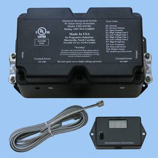
The Progressive
Industries model 40240 (50-amp model, $494) is available at Camping
World and other outlets. I highly recommend this capability – not only
do you know what is going on with your AC loads, but you are protecting
your coach AC system. From a design perspective, I prefer placing the
40240 directly “next to” the loadcenter if you are using a sub panel. If
wiring the inverter in-line then place the management system before the
inverter. This will offer protection to the inverter from surges and
spikes.
Back to Page Contents
Sample Systems
The sample systems I've configured here are just that - samples. You may
not agree that they are the best combination of components for your
particular situation. Everything is a tradeoff when it comes to RV's and
this area is no different. However, these should give you a good place
to start when you configure your own system. There are also
some detailed sample systems (with pricing as of 5/2007) that are a little different in the
downloadable Excel file
Solar Bill of Materials.
High-end System
For the individual
who boondocks a lot, and wants a technically superior system, that is
easily expanded. This is a top-end system that no one would
be unhappy with. Cost is not the major consideration - it is not
cheap. If you really push your system and need the best, then this is
(arguably) it.
-
Outback FX2012 Sine Wave Inverter 2000 watt/50 amp pass thru
-
Outback MX60 PV charge
controller (MPPT)
-
Outback Mate Monitor
-
4- Kyocera KC-130 Solar Panels. Hook them in series/pairs if long wire
runs. Best price/size/performance tradeoff. You can add lots more
panels with the 60 amp controller.
-
6 – LifeLine GPL-4C 6 volt AGM
batteries (660 Ah rating) or 6 – Trojan T-105 6 volt batteries (675 Ah rating)
Medium System
For those who want
good performance, but price is more of a consideration. The system is
not as easily expanded as the high-end system.
-
Xantrex RS2000 Inverter (on 30
amp system), or RS3000 Inverter (on 50 amp system). Both are Sine
Wave.
-
Xantrex SCP (System Control
Panel), and Trimetric 2020 monitor.
-
Blue Sky Solar Boost 3024i
charge controller (30 amp MPPT). Can handle 24-volt input.
Add the IPN Pro-Remote display for battery monitoring. If you
want more expandability there is a 50 amp version.
-
3 - Kyocera KC-130 Solar Panels. Best price/size/performance tradeoff.
You can add one more panel with the SB3024i controller. If you need
more than 4 panels later, then you can add another controller and
network them.
-
4
– Sam’s Club 6 volt Golf Cart batteries (410 Ah rating). Expand to 6
if you need more reserve, but you will probably want to go with an
extra solar panel if you have 6 batteries.
Economy System
For those who want good
performance, but price is the major consideration. The system is expandable,
but uses lower-cost components.
-
Heart (Xantrex) 458 Modified Sine
Wave Inverter 2000 watt/30 amp pass thru.
-
Trace C40 charge controller. PWM
controller, not an MPPT. Can handle 24-volt input.
-
Link 1000 Monitor. Has cumulative
amp hours.
-
3 - Kyocera KC-130 Solar Panels. Best price/size/performance tradeoff. You can
add three more panels with the C40 controller.
-
4 –
Sam’s Club 6 volt Golf Cart batteries (410 Ah rating). Expand to 6 if
you need more reserve, but you will probably want to go with an extra
solar panel if you have 6 batteries.
If I were building a new system
for myself I would build the medium system with the RS3000 inverter. I would add an extra
solar panel (4 total), and use 6 batteries.
My current system is similar to the economy
system, with a Trace C60 PWM charge controller and four KC-120
panels feeding 4 Sam's Club golf cart batteries.
|